1
$\begingroup$

I have asked this question in 3DPrinting.stackexchange forum but got no answer answer. Please take a minute to see if you can help.

I am building a simple RWD vehicle using 3d printer parts. See the picture below. RWD vehicle with steering
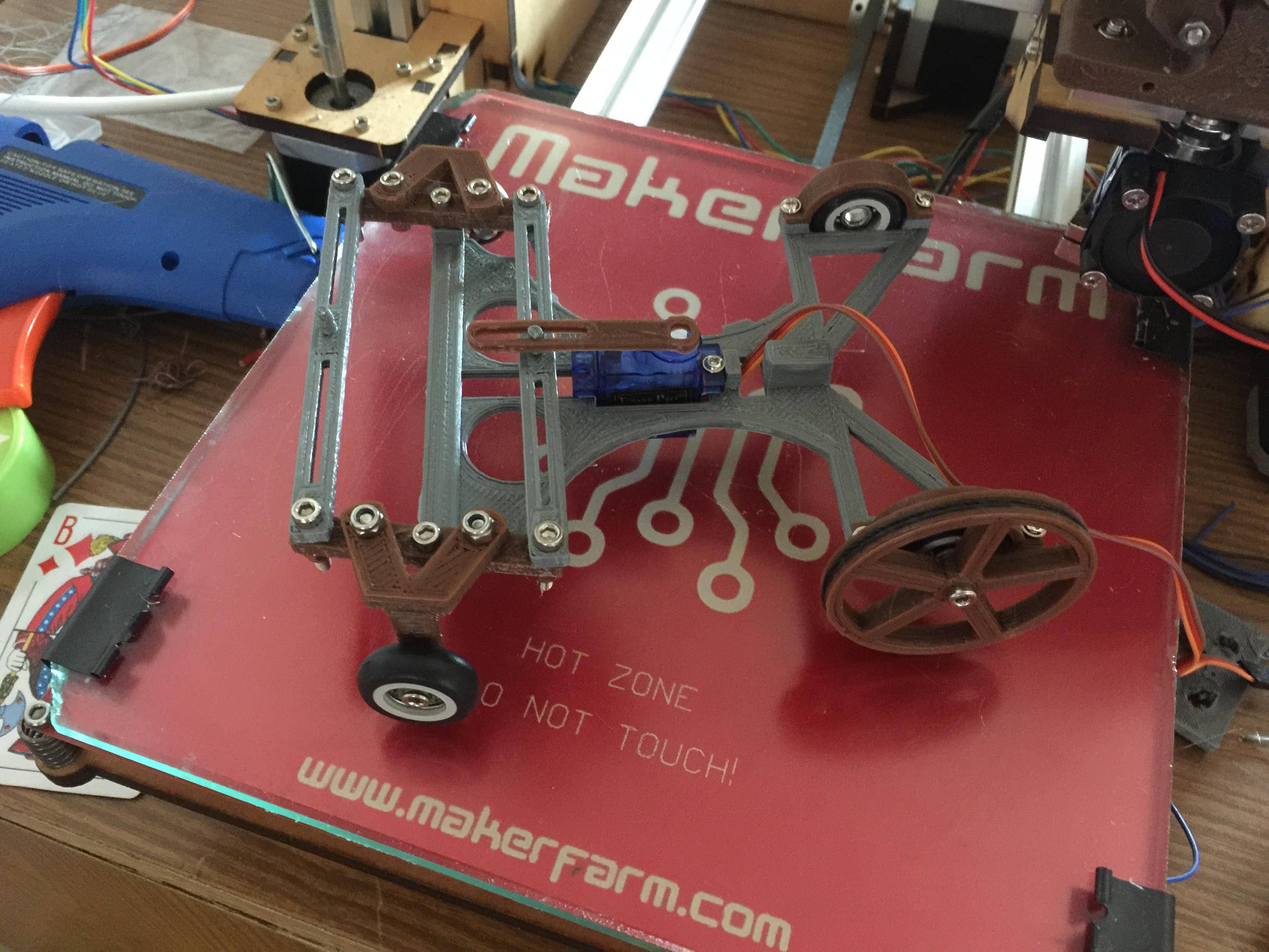
As you can see from the picture, I am using 3d printed linkages for steering mechanism and I used regular bolt and lock nuts to secure them together (thats what I had laying around the house at the moment). The problem here is that, holes in the linkages are not exactly the size of the bolt, and because the bolts are threaded, it generates a lot of friction. Other than that, the bolt seems to sit loose inside the hole and creates an unstable pivot. enter image description here
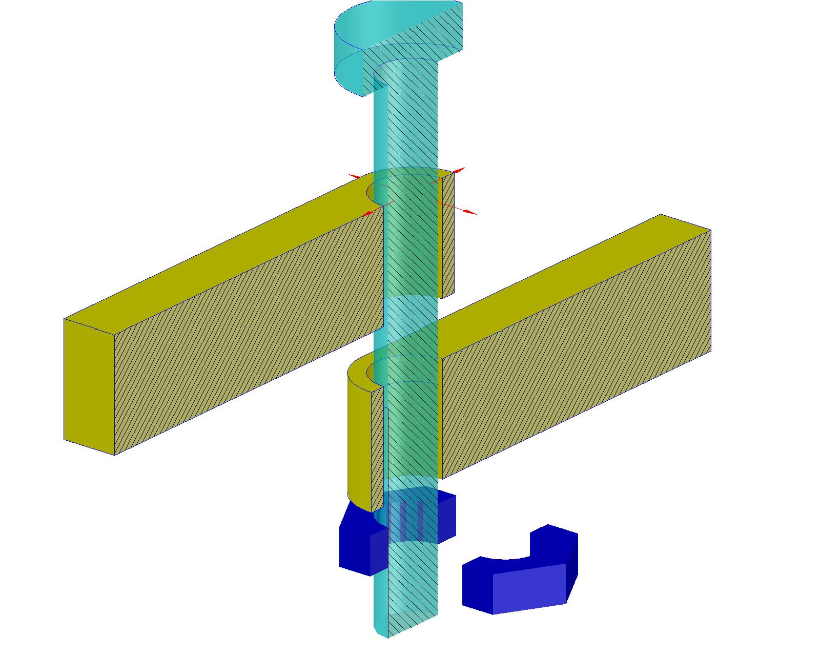
If I tighten the nut more, it just presses them together making it hard for the servo to operate. I am looking for a solution that will use simple bolts, nuts and washers which can be bought easily off the shelf (or even with the bolts and screws everyone has around there house). What can be done to make this joint stable in xy plane, rotating freely around the bolt. By the way, even though I used nylon lock nuts, it seems to loosen after couple of repetitive rotations.

Thanks for your help in advance and I hope ya'll have a great day.

$\endgroup$

1 Answer 1

0
$\begingroup$

Simple, easy but lower-quality approach: two nuts and a tension washer between them. Turn the nut until the linkages are secured in position with correct amount of play. Put the tension washer and a second nut, then holding the first nut immobile with a wrench, tighten the second nut very firmly. That way the pair of nuts will remain in place on the bolt without moving either way. Put a flat washer between the linkages; friction of 3d-printed plastic against 3d-printed plastic is much higher than plastic against metal.

Better quality, harder approach: nut-based bearings. Drill in the holes of the linkages, to size a little smaller than the nut. Heat the nut to temperature sufficient to melt the plastic, and place it in the hole, fusing it with the linkage. Screw the bolt in; leave some room between the linkages - about 2 turns worth. Secure the bolt by tightening it to one (top-most) nut, so that it's immobile relative to one of the linkages; the nut in the other acts as a bearing; it will introduce some half a millimeter of travel up or down as it turns, but that should be well within your tolerances.

Of course the best approach would involve actual ball bearings, but it seems for your application that might be an overkill.

$\endgroup$
1
  • $\begingroup$ Thanks for your response. Nut based bearing is actually a pretty good idea. I will try doing that and post the result. I am all in for using ball bearings, but micro sized bearings are hard to find or too expensive to purchase. I am using regular small sized bearings for front and rear wheels. $\endgroup$
    – user6120
    Commented Feb 20, 2017 at 12:00

Your Answer

By clicking “Post Your Answer”, you agree to our terms of service and acknowledge you have read our privacy policy.

Not the answer you're looking for? Browse other questions tagged or ask your own question.