1
$\begingroup$

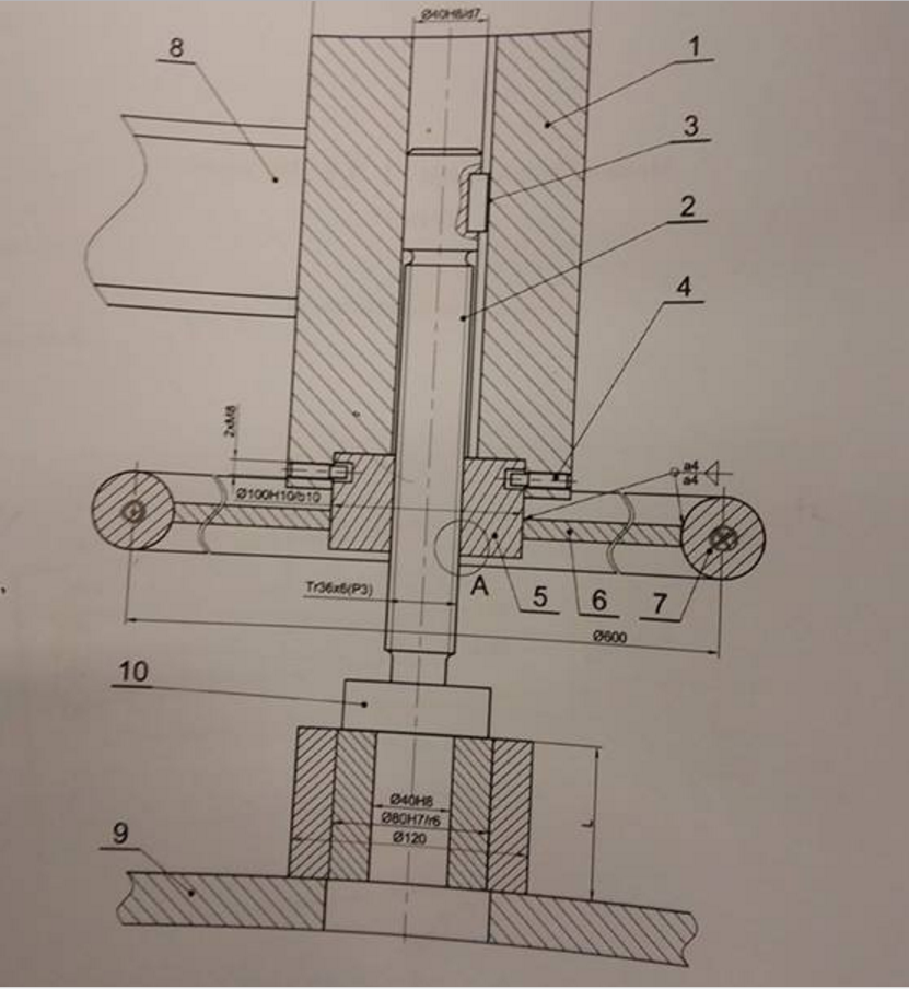
enter image description here

So this is a screw press used to hmm disconnect the clamp connection (sorry if these are not the correct terms I really don't know how to translate it properly). Anyway, I think it's obvious what this is used for to anyone familiar with the matter.

I need to draw the detail A

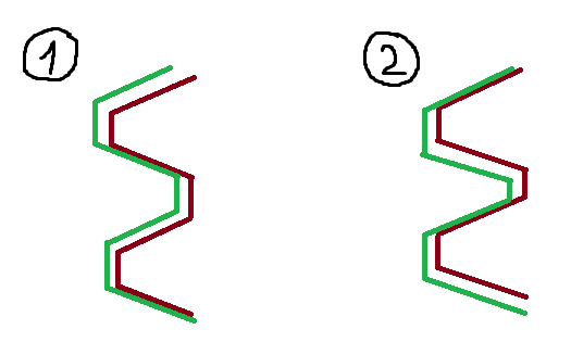
There's a big discussion among my friends on how it's supposed to be drawn. There are two options shown on the picture below, which one is correct?

enter image description here

Obviously, I used green color for the screw and red color for the nut.

Those who think case no 1 is correct, think that that screw teeth press upwards because of the reactive force that the clamp connection is giving.

Those who support the case no 2 think that since you are 'pushing' the inside of the clamp connection downward, then the teeth of the screw also push down on the nut teeth.
$\endgroup$
1
  • 3
    $\begingroup$ As we don't have legends on any of the parts we can only guess what's exerting force on what. But if 7 is pressing 10 down onto 9, then 7 must be exerting downwards force on 10 by pressing on 10's upper surface. Of course when it's releasing, the reverse will be true. $\endgroup$ Commented Feb 2, 2017 at 11:35

2 Answers 2

1
$\begingroup$

Screws are effectively a spiral wedge so when the screw is exerting a downward force case 1 is more representative. Case 2 would only be correct if there was an external force pushing on the back of the screw shaft.

Having said that it is not the convention to draw screw threads in this way. The gap and contact area between threads is defined by the thread standard and tolerances which are better indicated by notation rather than trying to draw them. In many cases it is simply not possible to draw tolerances to scale. Usually threads are drawn using some sort of abbreviation, of which there are various levels of detail.

$\endgroup$
0
$\begingroup$

It depends on:

  • The damping your system (if it is rusted or not)
  • The speed wants to bring it down

An experimental way to verify which of the case 1 or 2 apply could consist in removing the 'nut' and then let the system freely falls:

For every movement slower than this falling speed, the case 1 will apply (gravitation is the main force in the system)

For every movement faster than this falling speed, the case 2 will apply (Your system does not goes down naturally and therefore you are pushing it downwards)

Except if your system is rusted or incudes safeties to prevent free fall, the case 1 is most likely correct

$\endgroup$

Your Answer

By clicking “Post Your Answer”, you agree to our terms of service and acknowledge you have read our privacy policy.

Not the answer you're looking for? Browse other questions tagged or ask your own question.