I'm my engineering drawing course, do I need to mention and show every dimension in the diagram if I've drawn everything to scale and also written the scale below?
-
3$\begingroup$ It depends on the person who will be reading your drawings. In a class, you should ask your instructor. In real life, you should ask the facility, which will be fabricating parts per your drawings. $\endgroup$– Nick AlexeevCommented Aug 18, 2016 at 17:26
-
1$\begingroup$ I'm not qualified to give a definitive answer on this, but I've dabbled in it enough with my own personal projects to think that any critical dimensions should still be called out directly, including their tolerances, just to emphasize to the fab shop that you care about those ones specifically. In the case of automated manufacturing that takes your drawing/model directly, it can still be useful to provide a few dimensions on a different layer (that the machine doesn't see) for spot-checking. $\endgroup$– AaronDCommented Aug 18, 2016 at 21:54
-
$\begingroup$ I'm not sure if you're asking whether anyone would simply measure out on the drawing and then apply the reverse scale to get any necessary dimension, but if you are, then in almost all cases the answer would be "no". The only time a scale drawing might be measured that I'm aware of is when it's a map or floor plan, and in the latter case that would never be done for actual construction. A contractor might measure a drawing and apply the reverse scale to estimate lengths of cable, conduit, or pipe needed for a job. That's the only real world case I've seen. $\endgroup$– Todd WilcoxCommented Aug 19, 2016 at 2:32
-
$\begingroup$ I want to clearly state that this question (and its answers) seem to be specifically related to machined parts and things of that sort. The ability to scale or proper use of scaling is very different in other areas (e.g. grading/site work or buildings/architecture). $\endgroup$– hazzey ♦Commented Oct 3, 2016 at 14:51
6 Answers
As with many questions, the real answer is "it depends." The biggest variables are what kind of engineer you are, who your audience is, and what industry you're working in. In a class setting, it is probably a good idea to consult your textbook or your teacher for their opinions in the context of the class, but here are some general factors in making the decision when you don't have someone to ask. In industry, if I know the department or company that is going to do the actual work, I do usually ask them what information they need and try to tailor the drawing to them. More formally many companies will have internal policies or follow consensus standards like ASME Y145 or the ISO ICS 01.100 series. But often, you won't have that luxury. Maybe you are drawing something to go out to competitive bid, or for a project that has no manufacturing pipeline set up yet. In this case you have to make decisions based on the context. A number of other answers here provide good guidelines for relatively conventional machined parts, but don't necessarily address other types of drawings you may need to produce.
The general hierarchy of dimensioning goes like this:
Dimension critical features: These are the items that must be right for your object to serve its purpose. For example if you are drawing a sprocket the center bore must be correct, or it will not fit on the shaft. For mechanical drawings, you should pay particular attention to the tolerances on these dimensions and make sure they are very clear. Make sure you are dimensioning what really matters to you, even if this isn't the most convenient way to dimension it for your audience. In architecture and some other disciplines, you can also add "HOLD TO" to the dimension, to indicate that other dimensions may have to be adjusted slightly to make this dimension correct.
Dimension all functional requirements: These are all things that matter to your design, but are not as essential as your critical features. You should make sure that they are dimensioned and clear, but you don't have to draw extra attention to them like you do with a critical dimension. For example on the sprocket, the thickness of the sprocket needs to be machined correctly for it to fit, but it won't be a very tight tolerance.
Dimension things your audience needs to know: In many designs there are some aspects that are arbitrary. Maybe in your situation the thickness of the sprocket hub doesn't matter at all - it's under very little load and going in the middle of a big empty shaft for example. All the same, you should dimension it so that the person making it doesn't have to make the choice for you. If you want to allow them to make some economical decisions (eg start with a material size they have in stock) you could chose to put a very wide tolerance on the dimension. If it impacts what the next person has to do, you should provide some information.
Note the this section can be a little different for different industries. Machinists for example are used to having a part fully defined on a drawing so there's no guesswork for them to do. On the other hand if you are drafting a stud wall for a carpenter to frame out in a building, you would typically show them the minimum stud spacing, any special conditions (doorways, windows, etc.) but not every other detail. For example, it typically wouldn't matter to the engineer which side they started the studs from and where they ended as long as there is no gap greater than you specified. It might be easier for them to start from the north side because that's where the lumber is, or easier to start from the south side because the adjacent wall has already been framed. They might get clever and start the pattern centered on the wall to save one stud's worth of material. As long as the drawing contains all of the dimensions that matter to you, it's OK to leave it under-defined in this situation. For this step, it is really helpful to understand the process that someone else will be using to make your part whether it's machined, welded, carved, molded, etc.
Dimension things that other audiences would like to know (optional:) Often there is useful information you could provide, even though it doesn't matter to the person you're sending the drawing to. In the sprocket example, the machinist won't care what the pitch diameter is if you've already given them the profile to cut. All the same, you might decide to add it. This information will be useful if another mechanical designer wants to use your sprocket and comes across your drawing first. Generally since these dimensions are just for information, not an instruction to the next person, they will be indicated as reference dimensions. That should be done by placing them in parenthesis or adding the abbreviation 'REF' after the word.
Once all of these dimensions are listed, and the appropriate tolerances, materials, processes, etc are specified, your drawing should be complete. Now it's possible that if your object is complicated, the drawing will be cluttered with lots of dimensions that may seem redundant. There are a few options to reduce the total number of dimensions but retain the important information. This list is certainly not exhaustive, but it should get you started in most applications. Note that some of these make more work for your audience, so they may not always be received warmly.
- Patterns: If your features follow a grid pattern, it is sufficient to dimension one object in each row/column rather than each item. Similarly if your objects are all distributed rotationally around a point, you could dimension the circle they fall on and the spacing between them. Then as long as one starting position is given, the next person can construct the rest of the pattern.
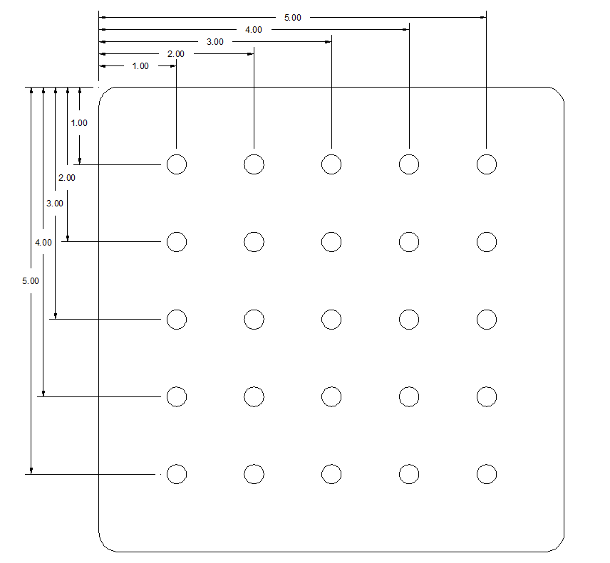
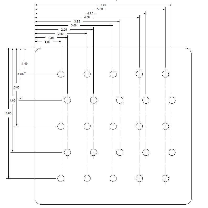
When the pattern is not obvious, it's a good idea to provide dotted lines that clarify which features are in the pattern and which aren't.
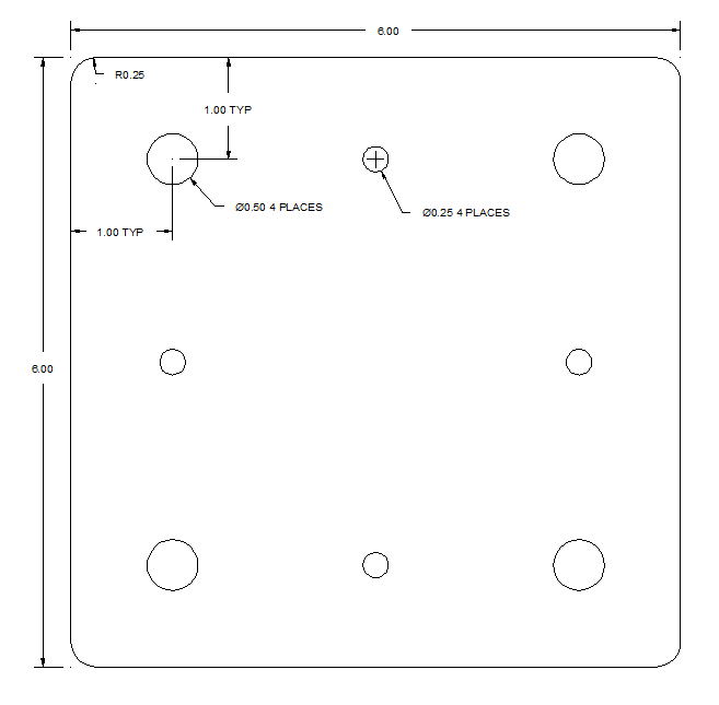
- Typical: If your drawing includes many features that match (entirely or in some aspect) you may dimension one and add "TYPICAL" or just "TYP" after to indicate that everything that looks like that, is the same as that.
Similarly if a feature appears more than one place, you can describe the number - give the details on one location and then specify "8 PLACES" for example.
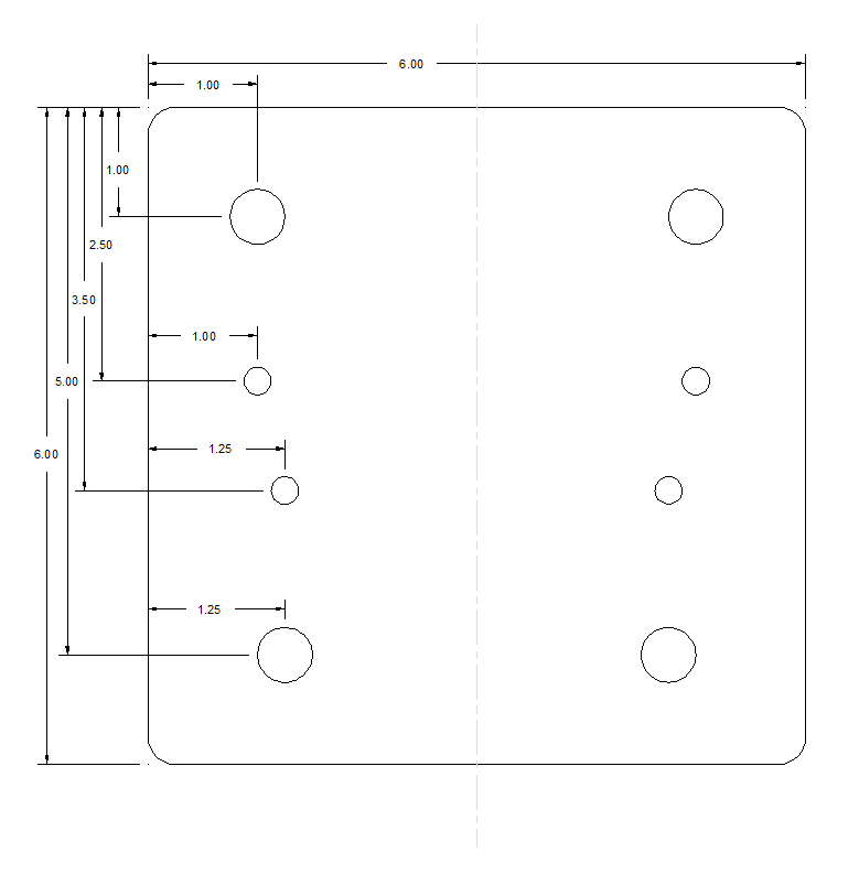
- Symmetry: If your object is symmetrical, you need only dimension one half of it, and then show a center line.
- Profile-controlled Geometry: When a feature or part is truly too complex to dimension clearly, even after you have considered detail and auxiliary views, your best bet may be a profile tolerance. With this option, you will provide a (digital) model of the curve or surface to your audience, and your drawing will show the shape without any actual dimensions. A profile tolerance block should be used, which indicates that the dimensions are controlled by the profile and gives your audience information on what the tolerance is. Using a profile dimension on an object that you could dimension reasonably easily would come across as lazy and unprofessional, so save this for truly complex shapes! More information on profile tolerances is available here and here. Note that even when you aren't using profile controlled geometry, you may still give a copy of your digital file to the shop you are working with as a courtesy to speed up their process. In general if you provide a properly dimensioned drawing, it will be considered to supersede the computer geometry unless you specifically agree otherwise.
Lastly, there are a number of good textbooks on drafting that will go into much more detail with better examples and style guidance. One that I would recommend is Technical Drawing with Engineering Graphics (Giesecke et al.)
I am not a professional engineer yet, but in my engineering design courses we were taught to show certain dimensions. For example, you choose a datum line and show certain dimensions. You don't need to label every single dimension, but you should show your dimensions in a way such that the dimensions which are NOT shown can be calculated arithmetically.
For example, if you have a single line, with 4 points starting at A and ending at D with B and C somewhere along the line, and A is your datum, then you could just show the dimensions for A-D, A-B and A-C.Simple arithmetic will then allow you to calculate the distance from B-C, for example (by taking A-C minus A-B). I believe this is done so that the person looking at your drawings doesn't* need to get a ruler out to check the dimension!
-
2$\begingroup$ +1, but I'd add that many engineers I've worked with (and I agree with them) prefer to put all the dimensions which might be useful, even if some of them end up being "redundant". This limits the risk of accidental arithmetic mistakes. So long as you don't take it to the extreme and the drawing becomes cluttered, the more information, the better. $\endgroup$– WasabiCommented Aug 18, 2016 at 13:52
-
5$\begingroup$ Adding to @Wasabi's comment, redundant dimensions are often labelled differently from other dimensions, for example I've seen "reference dimensions" surrounded by parentheses like so: (100). It's important to indicate which dimensions should be prioritized/must be exact during construction and which ones are there for reference, especially when you are indicating things like machining tolerances $\endgroup$ Commented Aug 18, 2016 at 14:56
My general philosophy is that you don't need to dimension everything, you just need to dimension every unique feature.
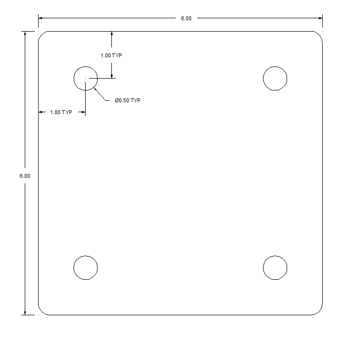
For instance, say you have a bolt pattern, with one hole in each corner. You give the dimension for every offset for the holes, but this is more information than required.
The way I do it is to show bounding dimensions for the plate, dotted lines to indicate vertical and horizontal centerlines (no dimensions there as it's understood they're half the bounding dimensions), then just show the distance from each centerline to one hole. For the hole, have a callout that gives the hole diameter and tolerance and/or threading requirements. Again, if all four holes are the same, then just use, "4x 6mm Thru All" or similar.
Machinists are some of the smartest people on the planet. My preference would be to give a clear, concise set of drawings to them and then, if I've forgotten a dimension, they can write back and ask.
So to recap, I gave 5 dimension - bounding X, bounding Y, centerlineY-Y, centerlineX-X, and hole diameter. That gives everything to produce the plate and four holes. If you have fillets on the corners (try to avoid ever making something with sharp edges unless you need to!) then that's one more dimension - 6 total - four eight features.
You can get away with this because you dimension the unique features. One hole and one fillet on a square plate - the rest are clearly symmetric. The only time I would start adding more dimensions than that is if there are so many features that it could be confusing as to which features are members of a pattern and which aren't, or if there are offsets or jigs in the base material that would make patterning more difficult.
If that is the case, then again my personal preference is to have one sheet per pattern or set of unique features. If you've got a part that has through holes, threaded holes, and some slots or something, then one sheet gives bounding dimensions for the part plus dimensions for the through holes, the next sheet gives dimensions for the threaded holes, etc.
5 minutes of a machinist's time is a couple reams of paper, so keep the drawings clean by using as many sheets as you need to in order to dimension all of the unique features.
A couple of parting notes:
- Use the machinists. Explicitly ask for a critique on every part and drawing you produce. You should, if at all possible, talk to them in advance about what you want to do and how you're planning on doing it. See the earlier comment: machinists are brilliant people.
- This goes along with the one pattern-per-sheet rule of thumb - don't ever, if at all possible, make a drawing for an 8.5x11 sheet of paper. Use the 11x17 or larger format. Again, the more legible you can make your work, the better for everyone involved. I think, if you ever see a set of your own drawings on 11x17, you'll never go back.
Yes, with the caveat as supplied by masiewpao's answer that dims which can be calculated directly from supplied dims can be left off.
The reason you must write in the dims is that "to scale" is purely qualitative. Nobody ever puts a scale on drawing to guesstimate the dimensions. The reasons why not should be obvious :-)
-
4$\begingroup$ Just to spell out some of the reasons if they are not "obvious": There are many ways to reproduce drawings on paper (or computer displays) that don't maintain 1:1 scale, and many consumer-quality photocopiers and printers don't have exactly the same scaling in the X and Y directions. Even if you avoid those problems, "ordinary paper" isn't dimensionally stable, and it changes size by different amounts along and across the "grain" of the paper as the humidity changes. $\endgroup$ Commented Aug 18, 2016 at 14:07
It very much depends on the context. Drawings are there for a purpose ie to communicate information and you need to keep that specific purpose in mind when producing the drawing.
For example if you are producing a drawing for the manufacture of a part then you need to think about what information is needed for the manufacturing process.
I know from experience that it is possible to have a drawing which isn't actually missing any information as such but the dimensions have been assigned in such a way as to be very unhelpful.
It is difficult to generalise but you need to think carefully about the specific information that the person using the drawing needs as far as is practical this should be presented clearly on the drawing.
As mentioned in another answer it is often best to present dimensions relative to a few well defined datum lines or points rather than stacking them on top of each other but again the context and especially the manufacturing process involved makes a difference.
Having to scale by measuring from a drawing is usually bad practice as it tends to introduce extra errors, especially if a drawing is reproduced or handled a lot. any dimensions not shown should be easy to deduce by simple addition or subtraction.
One should never ever measure things from a drawing. There are several reasons for this:
- The printer was misconfigured, and the output is no longer in scale. This happens a lot. Even if not the printer has a limited resolution so very small details may be off anyway.
- The measurement may be inaccurate maybe the dimension in question is 10.1mm but the machinist measured from the drawing and interpreted it as 10mm. Bad! Also for longer spans the measurement may be a bit skewed etc.
The drawing is an acceptance document, what you're documenting is the acceptance criteria. You should thus have all the dimensions that matter to you marked out. Otherwise you may need to pay for all manufacturing defects.
You should not mark out all dimensions just so much that the dimension loop is complete. So to not introduce conflicting information in the drawing. If you just add those dimensions put them in parentheses. This may be useful for the machinist if the acceptance criteria is not really useful for machining for some reason (this can be bad for very accurate parts though).
If you totally leave out a dimension loop then you are leaving things to the machinists judgement. While this may not be bad as such, you're letting somebody else do the thinking in a way that produces something spectacularly different from your needs. Most shops would not accept such jobs but your local machinist might.
But no you should try to add as few dimensions as possible that captures what your needs are. And suplement with as much data as the manufacturer needs to get things done.
