0
$\begingroup$

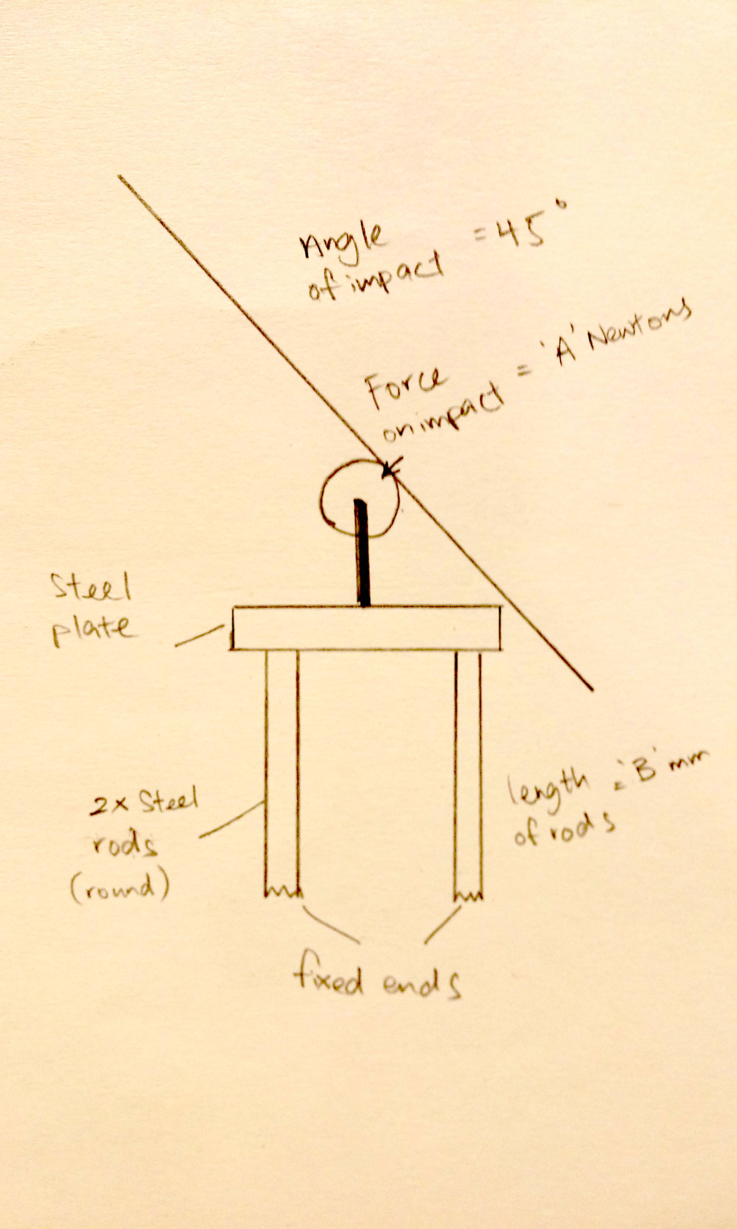
As in the picture below, there is a static force $A$ being applied at 45 degrees to a rigid rod attached to a rigid plate. The plate is supported by two rods of length $B$ and diameter $D$, each of circular cross-section, which are fixed at their ends opposite the plate. The force is applied halfway between the two rods. The weight of the objects are negligible.

Diagram.

See here for a more precise diagram, but note that there should also be a bending moment at the point where the load is applied due to the parallel-axis theorem.

The objective is to determine the deflection in each of the two rods. Assuming no other parts in the picture other than the two rods deflect, how do I determine the deflection of the two steel rods?

Edit: I think a better way to visualise it is that it is kind of like a cantilever; where the two fixed ends are like attached to a wall. This was how I saw the problem.

$\endgroup$
5
  • $\begingroup$ See if you like this diagram, its a bit more engineer-y: imgur.com/iyddGnB Cross-hatched is fixed and rigid, gray is rigid but not fixed, point force A, length B, round x-section with diameter D. $\endgroup$ Commented Dec 30, 2015 at 17:57
  • $\begingroup$ I'm assuming the problem is static, and thus reasonably solvable analytically. $\endgroup$ Commented Dec 30, 2015 at 18:01
  • $\begingroup$ @starrise yeah, that looks pretty good thanks! $\endgroup$ Commented Dec 30, 2015 at 23:01
  • $\begingroup$ It's worth noting the new drawing is not the same as the previous one, since the force was simply transported from the top of the rod to the plate. Due to the parallel axis theorem, there should also be a bending moment applied at the new application point. $\endgroup$
    – Wasabi
    Commented Dec 31, 2015 at 1:19
  • $\begingroup$ I have rolled back the post to display the old drawing, leaving the incorrect diagram as a link. $\endgroup$
    – Wasabi
    Commented Dec 31, 2015 at 1:25

2 Answers 2

2
$\begingroup$

EDIT: Looking back at this answer I realize that the entire method is flawed. The final answers for $M_B$ and $B_y$, however, are correct. However, I believe this cannot be proven without FEA software or the direct stiffness method, which would be too lengthy and complex to present here.

This can be solved once you know your structural analysis. You'll need to solve the entire structure for its internal forces and then you can calculate each of the rods for their deflections.

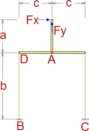
Take this as your structure:

enter image description here

We can immediately realize that the vertical component of the applied load won't affect anything in the rods other than their axial loads, so we are going to sideline it for now and pretend we only have a horizontal load. We'll remember it later on. This only works because the horizontal bar is defined as rigid in your question.

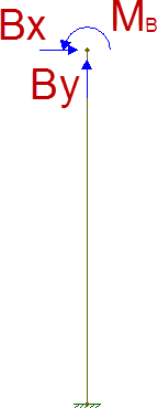
Also, the shear force along each of the two rods will be constant and equal to $B_x = C_x = -\frac{1}{2}F_x$. Also, the moment due to the applied force will be resisted by the fixed ends but also by a force couple of the axial forces on the rods.

The total moment around point C is equal to (observing the fact that $M_B = M_C$ and $B_y = -C_y$):

$$\sum M_C = -F_x \cdot (a+b) - 2 \cdot B_y \cdot c + 2 \cdot M_B = 0$$

So we need to find $F_{y,B}$ or $M_B$ to solve the entire structure. To do this, we need to list what we know.

  • The shear force along the rods is equal to $\frac{1}{2}F_x$. This means that the total change in moment along the rods will be equal to $b \cdot \frac{1}{2}F_x$.
  • The axial forces in the rods ($B_y$) will turn to shear forces in the horizontal bar, meaning there will be a change in moment along the horizontal bar from point D to A equal to $B_y \cdot c$.
  • The bending moment around point A for the vertical rod is equal to $a \cdot F_x$. Since point A is in the middle of the horizontal bar and the axial forces in the rods are equal in magnitude, this bending moment will be equally split between both sides of the horizontal beam.

So now we know that the bending moment diagram from point B to point A will have to go from $M_B$ at B to $M_B - b \cdot \frac{1}{2}F_x$ at D to $-\frac{1}{2}a \cdot F_x$ at A. Since we know that the change in moment from D to A is equal to $B_y \cdot c$, we can conclude

$$M_B - b \cdot \frac{1}{2}F_x + B_y \cdot c = -\frac{1}{2}a \cdot F_x$$

Using this and the sum of moments around C, we can solve for $M_B$ and $B_y$: \begin{align} M_B &= \dfrac{F_xb}{4} \\ B_y &= -\dfrac{F_x(2a+b)}{4c} \end{align}

We must then just remember the vertical component of the applied load and add it to $B_y$ , which therefore becomes $-\dfrac{F_y}{2}-\dfrac{F_x(2a+b)}{4c}$. $C_y$, meanwhile, becomes $-\dfrac{F_y}{2}+\dfrac{F_x(2a+b)}{4c}$. Once you know the internal forces in each of the rods, you can then calculate the deformations due to these. Since you don't define which deflection component you're after, I'll leave that part to you.

To make it perfectly clear, you need to calculate the deformations under this condition:

enter image description here

All figures created with Ftool, a free 2D frame analysis tool.

$\endgroup$
3
  • $\begingroup$ This doesn't take acceleration forces into account, nor does it account for bending in Aa or DA. The applied force is not static. $\endgroup$
    – Chuck
    Commented Dec 31, 2015 at 22:30
  • $\begingroup$ @Chuck The question states "[...] there is a static force $A$ being applied at 45 degrees [...]" Looking at the edit history, the OP previously stated "Edit: [...] For this example, let's take this as a static loading." I do believe these were added to the question after your answer. $\endgroup$
    – Wasabi
    Commented Jan 1, 2016 at 15:25
  • $\begingroup$ @Chuck, also, if by "nor does it account for bending in Aa or DA" you mean that the plate and center rod are considered rigid, that is also because the question specifically states "Assuming no other parts in the picture other than the two rods deflect [...]" $\endgroup$
    – Wasabi
    Commented Jan 2, 2016 at 3:03
0
$\begingroup$

How accurate are you trying to be?

Assuming the roller is ideal, it won't allow a torque, so resolve the impact force to x/y component forces at the center of the roller.

Assuming the base of the black roller pedestal is fixed (if the legs are going to flex, then it's not!), then the x/y forces at the top of the black pedestal will resolve to an x/y force and a moment at the base of the pedestal.

If the steel plate doesn't flex (if it's real, it will!), then it will transmit the forces and moment to the tops of the rods. You can then look up the formulas for deflection for the loads and sum the results.

But again, if the legs flex, the black roller pedestal will move. You are calling the force an "impact", which implies that it is a short-term, dynamic load.

An impact has an impulse profile, which shows force plotted over time. The area under the curve (integral) gives the impulse, which is typically constant for a given impact regardless of the "springiness" of the collision. A springy surface increases the impulse duration, reducing the peak force. This is why hitting an airbag is better than hitting a wall - lower peak force, even though both will bring your face to a stop.

All of this is to say that dynamic situations are extremely difficult to evaluate. These are typically done with numerical simulations, because dynamic deflection reduces the force transmitted at that particular instance.

Numerical simulations are used because you wind up with iterations around "loops" like the following:

  1. Assume nothing deflects, find max loading.
  2. Use that loading to deform the structural members.
  3. With the members deformed, the applied force is lower (because force times distance, energy, "drains" kinetic energy from the impact source)
  4. Run the process again with the lower applied force.
  5. Get new deflections, those get a new impact force, repeat, repeat, repeat.

Eventually this should stabilize at a particular deflection, but now that the structure has been deflected in some period of time there is an acceleration in the structure, which adds a force at each member that deflected.

If your question were about deflection under static load then I would say it's probably a suitable final exam question for a deformable bodies course (5th semester mechanical/civil engineering course). As it stands, this is more along the lines of a finite element analysis class, which would probably be a 4th year undergrad/graduate course.

Which is to say, if you are looking for accurate results, you're not going to find them here. You need to know more information about the source of the impact, the shape, size, material (including grade) of all of the structural members, a finite element analysis software package, and probably at least one class on how to use the software.
$\endgroup$
4
  • $\begingroup$ Thanks for your thorough explanation on the flaws of my question. I edited the question slightly, hopefully to narrow the scope of the question. $\endgroup$ Commented Dec 30, 2015 at 13:31
  • $\begingroup$ The thing I'm really unsure of is the fact that: 1. there are two parallel rods and 2. the load applied is at an angle. For two parallel rods, does this mean that the load is just simply equally distributed to both rods? $\endgroup$ Commented Dec 30, 2015 at 13:46
  • $\begingroup$ @FirzanArmani - The load may be applied to the roller at an angle, but because it is a roller there is no torque at the roller's pivot. This means that you only have two forces, X- and Y-directional forces. These forces act on the roller pivot. The fact that the force is angled just means you get a Y-directional force along with an X-directional force. If the force were strictly down it'd be 100% y and 0%x. If it were strictly sideways it'd be 0%y and 100%x. At 45 degrees, it's 70.7%y and 70.7%x - The sum of the forces is more than the whole because they are distributed by Pythagorean theorem. $\endgroup$
    – Chuck
    Commented Dec 30, 2015 at 13:54
  • $\begingroup$ 0.707^2 = 0.5. So, x^2 + y^2 = the whole, or 0.5 + 0.5 = 1. $\endgroup$
    – Chuck
    Commented Dec 30, 2015 at 13:54

Your Answer

By clicking “Post Your Answer”, you agree to our terms of service and acknowledge you have read our privacy policy.

Not the answer you're looking for? Browse other questions tagged or ask your own question.