4
$\begingroup$

I've attempted to answer the following question and I need to know if I am on the right track:

LOGIC GATES

Question 3

A manufacturing plant uses two tanks to store certain liquid chemicals that are required in a manufacturing process. Each tank has a sensor that detects when the chemical level drops to 25% of full. The sensors produce a HIGH level of 5V when the tanks are more than one-quarter full. When the volume of chemical in a tank drops to one-quarter full, or less, the sensor puts out a LOW level of 0V. It is required that a single green light-emitting diode (LED) on an indicator panel shows when both tanks are less than one quarter full.

3.1 Show the truth table

3.2 Derive the Boolean expressions.

3.3 Show how 3 NAND gates can be used to implement this

(Consider the wording very carefully in this question)

It's question 3.1 and 3.2. The last sentence of the main question is a bit tricky. It says "Show when both tanks are less than 1/4 full."

Here is my solution:

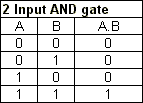
  • Both inputs (namely Tank A and Tank B) need to be LOW in order to indicate a LOW output
  • The only logic circuit to satisfy the above is an OR circuit.
  • 0 + 0 = 0; 0 + 1 = 1; 1 + 0 = 1; 1 + 1 = 1
  • From the above I believe OR operations is correct, since A and B are both LOW and thus causing the output to be low.

I was considering AND Circuit but then 0 x 1 = 0 and 1 x 0 = 0. These operations conflict with the question. The output must only show LOW when BOTH inputs are LOW.

Therefore my solution for 3.1 and 3.2 would be using an OR gate. Is that correct?
$\endgroup$
2
  • 4
    $\begingroup$ Instead of a photo, it's better to type in the question. Photos aren't easily searched and are blocked for some of our users by the companies they work for. $\endgroup$
    – user16
    Commented Feb 11, 2015 at 14:24
  • $\begingroup$ Here's our fledgling homework policy, FYI. But I think you've satisfied its requirements. $\endgroup$
    – HDE 226868
    Commented Feb 11, 2015 at 16:33

4 Answers 4

7
$\begingroup$

So let's break this down, piece by piece.

The output must only show LOW when BOTH inputs are LOW.

We also know that the sensors read High (5V) when the tank volume is above 25%.

| Tank 1 | Tank 2 | Monitor LED |  
|--------|--------|-------------|  
| High   | High   | Lit         |  
| High   | Low    | Lit         |  
| Low    | High   | Lit         |  
| Low    | Low    | Dark        |  

Please note: For the sake of this explanation, we're assuming 0 means low and 1 means high. So the logic diagram above is "upside down" from a traditional representation that starts low and iterates to high.

And if we look at a typical AND gate, we find that we're close but our logic is backwards.

AND gate logic

So let's introduce the NOT gate:

NOT gate logic

But if we put the NOT gate after our AND gate, we end up with a NAND gate and that's not the logic diagram we want.

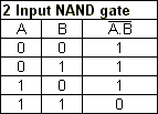
NAND gate image NAND gate logic.

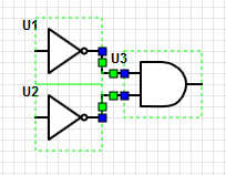
Dang! that brings us back to square one, right? Nope, not quite. What happens if we use two NOT gates and move them to the other side of our AND gate?

Inverted NAND

That seems to do the trick! Our High signals become Low, and our Low signals become High.

I'll let you work out the algebraic expressions for that diagram; it should be trivial to translate now.


The fun part is trying to express this using just NAND gates. The trick is to use the NAND gate as an inverter and realize that our logic is backwards from the voltage that's present.

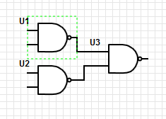
If we layout the three NAND gates like this:

3 NAND gates

And if Tank 1's sensor is fed to both gates of U1, and Tank 2's sensor is fed to both gates of U2, we're using the first tier of NAND gates as inverters. Looking at the logic diagram, we see that our green LED will be lit in the cases we want, and not lit in the case when both tanks are below 25%.

| Tank 1 | Tank 2 | T1 V | T2 V | !T1 V | !T2 V | 2nd NAND | LED |
|--------|--------|------|------|-------|-------|----------|-----|
| High   | High   | 5    | 5    | 0     | 0     | 5        | Lit |
| High   | Low    | 5    | 0    | 0     | 5     | 5        | Lit |
| Low    | High   | 0    | 5    | 5     | 0     | 5        | Lit |
| Low    | Low    | 0    | 0    | 5     | 5     | 0        |     |

You also asked:

Therefore my solution for 3.1 and 3.2 would be using an OR gate. Would I be correct on this?

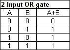
Looking at the truth table, with 0 for Low and 1 for High:

OR truth table

And that would work too. But using an OR gate doesn't necessarily set you up to easily understand how to use the NAND gate configuration.


If nothing else, this exercise should help you understand the duality in being able to express positive and negative boolean logic.

$\endgroup$
2
  • 1
    $\begingroup$ This is correct. However, the OP was asking for a hint to solve the problem. $\endgroup$
    – Niko Fohr
    Commented Feb 11, 2015 at 15:15
  • 2
    $\begingroup$ @np8 - I noticed that. Please look over our meta guidance on homework questions. meta.engineering.stackexchange.com/questions/121/… "Hint" answers aren't constructive and don't mesh well with the StackExchange Q&A philosophy. Either the question is worth answering or it isn't. Hints don't build lasting value for the site. In this case, the OP demonstrated an attempt to solve the problem and was stuck with understanding the logic. Also note that my answer took a different route than proposed by the OP. $\endgroup$
    – user16
    Commented Feb 11, 2015 at 15:18
1
$\begingroup$

The question is actually incomplete, since it doesn't specify whether a logical "low" or a logical "high" lights the green LED. Usually in such cases, you must assume that you need a logical "high" to light the LED. Therefore, your logic needs to generate a logical "high" only when both inputs are logical "low".

$\endgroup$
1
  • $\begingroup$ Yes I am aware of that. Until I get a reply from my lecturer, I'm assuming that a LOW (switched off) would indicate when both the inputs are LOW. Thanks for the reply. $\endgroup$ Commented Feb 11, 2015 at 13:51
1
$\begingroup$

First of all, be careful to only answer what you are asked. This will be relevant in your school work, but also during your professional career.

For example, your question "Therefore my solution for 3.1 [...] would be using an OR gate." is irrelevant in the case of the 3.1 question where you are only asked the truth table. As its name implies, a truth table is a table, which you already have a part of.

Also, usually in engineering, the answer to one question uses the output of the previous question. This scheme of thinking also applies to your professional life, where you divide your [big] problems into smaller ones more manageable.

I know I do not directly answer the question, but being able to see if you're on the right track (and find your mistake if you're not) is also an ability of an engineer.

$\endgroup$
2
  • $\begingroup$ Thanks for the advice. I only wanted to post my idea to the solution, to check if I'm on the right track. $\endgroup$ Commented Feb 11, 2015 at 13:59
  • $\begingroup$ If you follow my advices, you will realize that you mainly are. $\endgroup$
    – gromain
    Commented Feb 11, 2015 at 14:00
1
$\begingroup$

Therefore my solution for 3.1 and 3.2 would be using an OR gate. Would I be correct on this?

If the LED turn ON when the input for the LED is LOW, then yes.

I would assume that it is the other way around (a HIGH state would turn the LED on). Then you would just invert the output (i.e. use a NOR gate)


As an advice, DeMorgan's law might become handy when you are solving this.

$\overline{A+B} = \overline{A} \cdot \overline{B}$

$\overline{A \cdot B} = \overline{A} + \overline{B} $

$\endgroup$

Your Answer

By clicking “Post Your Answer”, you agree to our terms of service and acknowledge you have read our privacy policy.

Not the answer you're looking for? Browse other questions tagged or ask your own question.