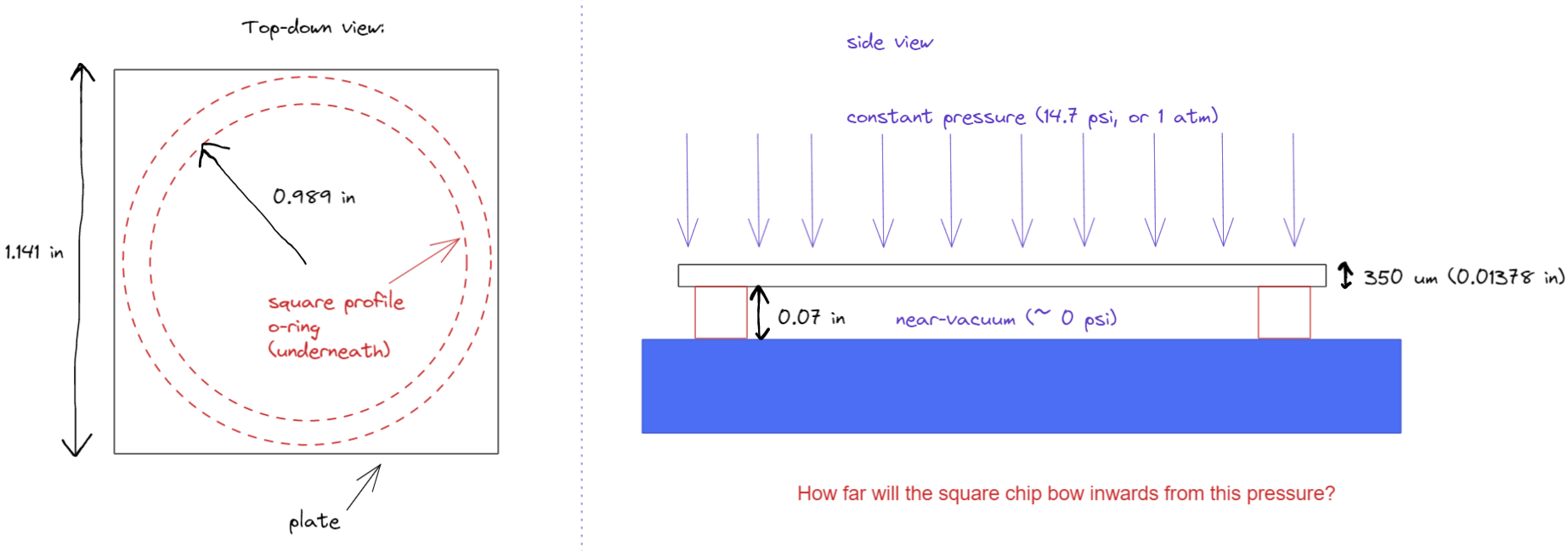
I apologize in advance for any mistakes in terminology or ambiguity in explaining the problem. I am conducting an experiment that uses the following setup and am trying to figure out how the system will behave, but I don't have any training in this sort of thing.
The system is as follows: I have a thin square chip that's 350 microns (0.01378 in) thick and 1.14 in to a side supported by a circular O-ring with inner radius 0.989 inches, as shown below. The cross-sectional profile of the O-ring is square with width 0.07 inches.
The square chip is on a vacuum chuck, so the underside is experiencing approx 0 psia (the pressure is likely on the order of 1 Torr or less). The top side is under atmospheric pressure (~14.7 psi). I am trying to figure out how much the chip will bow when the vacuum pump is turned on and the chip experiences this pressure difference.
I'm assuming the system can be treated as a circular plate of radius R simply supported at its edges (i.e. assume the extra bits at the square corners don't really affect the final result -- is this a fair approximation?). Based on Roark's formulas for stress and strain table 11.2 case 10a (flat circular plate of constant thickness, uniformly distributed pressure, simply supported) the maximum deflection in the center is given by
$$y_c = \frac{qa^4(5 + v)}{64D(1 + v)}$$
Where the flexural rigidity $D$ is
$$D = \frac{Eh^3}{12(1 - v^2)}$$
Let's say the chip is sapphire, so $E \approx 400 \mathrm{~GPa} = 5.8\times 10^7\mathrm{~psi}$, $v \approx 0.3$. Therefore, $D = \frac{5.802e7\mathrm{~psi}\cdot (0.01378\mathrm{~in})^3}{12(1 - 0.3^2)} = 13.90 \mathrm{~in~lbf}$ and the maximum deflection is $$y_c = \frac{(14.7)(0.989)(5 + 0.3)}{64(13.90)(1+0.3)} \approx 0.064 \mathrm{~in} $$
My questions are the following:
- Is this general process correct? Does the result make sense? I don't really have any intuition how much a very thin but very hard plate would bow in a situation like this.
- Is approximating the system as a simply supported circular plate valid? How significantly would accounting for the full square shape change the results? My guess is the actual deflection of the square plate (supported by a circular O-ring) would be slightly less than the circular plate approximation.
- The O-ring (specifically, this one, shore hardness 70A) is obviously not perfectly rigid, and I imagine it will compress some amount from this pressure. Based on this graph it seems the O-ring will compress somewhere around 20% of its original diameter, but I'm not really sure how to quantify this more accurately.
Thanks!
