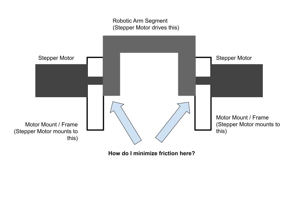
As drawn, you could nylon or oilite washers as spacers on the shaft between the white walls and grey-U. Second best would just be to use brass or bronze since you don't want aluminum rubbing on aluminum. That will promote a lot of wear and galling. Brass and bronze rubbing on pretty much anything else are much better for withstanding wear and galling. But this is all a bit slipshod since this will allow your setup to withstand stronger horizontal loads than vertical loads but your vertical loads are going to be higher than the horizontal loads. You have excessive strength where you can't use it. As drawn, where the the stepper motor shaft simply passes through a clearance hole in the white wall unsupported, the stepper motor bearings and their mounting bolts will take all the vertical load.
For best vertical load capability, your stepper motor shaft should rest on separate ball bearings that are inset into the white walls. Many bearings have the inner race a bit longer and wider than the outer race so it protrudes a bit. With proper positioning, the inner race will protrude beyond the white wall and the grey-U can rest against that to maintain a gap. Even if the bearing doesn't have this feature, all you need to do is get a small tube or thin ring with the same outer and inner diameter as the inner race and slip it over the shaft on that side and it will act as a spacer. In this setup the sidewall load capability is whatever the axial load the ball bearings can withstand and different ball bearing designs can withstand different amounts. Ball bearings by design will withstand higher radial loads (vertical loads in your setup) than axial loads (horizontal loads) but that's probably fine since your vertical loads are going to be higher than your horizontal loads. If you need extra horizontal strength then you seat the the bearings so they sit within the thickness of the white wall (remove any tube or ring spacers on the shaft, reposition the bearing, or select a bearing with no inner race protrusion), and add the aforementioned washers to transfer horizontal loads directly into the white wall rather than having the bearing take them.
And even if there are no ball bearings set in the white walls (the stepper motor shaft just passes through a clearance hole in the white wall completely unsupported such that the stepper motor bearings and mounting screws take all the load) you are fixing the grey-U to the shaft somehow anyways. So just fixing it so that the grey-U cannot slide along the axis of the shaft and position it so there is a gap between the white wall and the grey-U.
