1
$\begingroup$

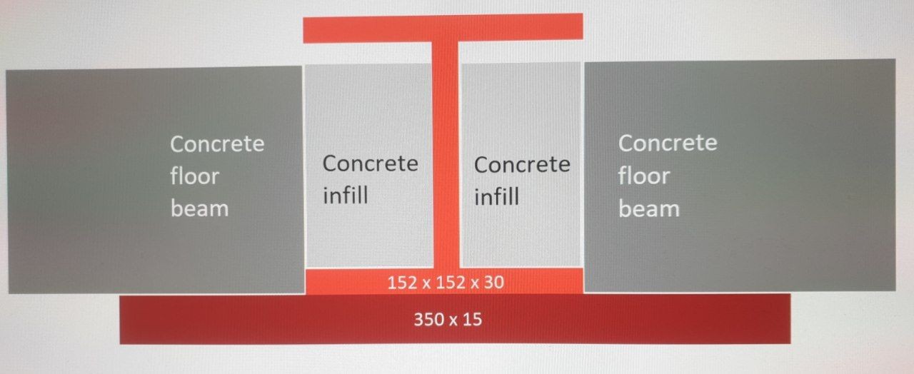
A common way of providing bearing for concrete floor-beams above ground level, is to create a "slimflor" style steel element, comprising an "I" beam with a steel plate welded beneath it (to extend the bottom flanges). The beam made, is usually fixed at both ends.

A typical combination might be 152x152x30 UKC with a 350x15mm plate welded beneath (6 or 8mm fillet welds), to extend the flanges on both sides.

enter image description here

Calculations for the "I" beam profile are easy - usual maximum deflection for a beam with the given load, and ensure checks for torsion/eccentricity are OK.

The steel plate width is also easy - the concrete floor beams require a certain bearing, usually defined in their specification documents. Typically 75 -200mm each side, plus a little for the beam web and for safety margin.

But the steel plate thickness, I can't find how this calculated. How do you know it needs to be 15mm thick, as opposed to 10,12, or 20 mm?

I can't find a document that authoritatively or convincingly summarises this calculation.

Help appreciated.
$\endgroup$

2 Answers 2

1
$\begingroup$

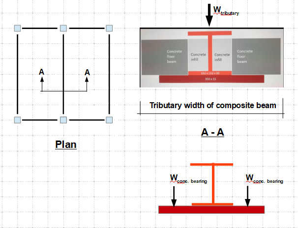
The steel beam is subjected to two conditions that are to be considered in the design:

  1. Composite with the concrete floor to carry the tributary floor load. You can find the plate thickness through the required properties of the composite beam.

  2. A built-up beam with the cover plate acting as the (cantilever) bearing support for the concrete strip in the direction transverse to the steel beam.

The thicker t from 1 or 2 above is the required thickness.

enter image description here

$\endgroup$
2
  • $\begingroup$ For clarity, it seems you are saying that one can actually assume (for design calc purposes) that the plate acts like a double cantilever, with each side conceived as either (1) a point load from the floor beams at the centre of the cantilever (your 3rd diagram), or (2) an equivalent UDL across the entire width of the cantilever. Is that correct? Is that how it should be done, under UK/Eurocode? $\endgroup$
    – Stilez
    Commented Dec 22, 2021 at 0:05
  • $\begingroup$ Actually, this is a strange design, and I don't know if this is per the UK/Euro practice, but, I would consider the plate acts as the concrete floor/beam seat, otherwise, there is no need for that a wide plate below the concrete. $\endgroup$
    – r13
    Commented Dec 22, 2021 at 0:14
0
$\begingroup$

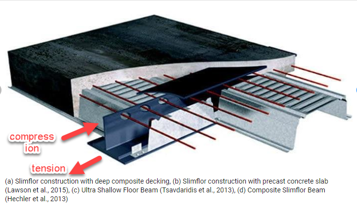
Slimfloor composite beam is the tension part of the composite beam that has the floor slab as its compression part.

So its size has to be solved and calculated by applying the appropriate floor loads to the assembly of the concrete flange on top, steel on the bottom. Then Calculate the moment and shear, and plug in the depth and section properties of the steel beam, any additional tension section needed to balance the beam is the area of the plate.

EDIT

After commenting by OP. Just very roughly as a conceptual illustration.

Let's say after applying the floor live and dead loads and load combinations as per code you have M for bending moment.

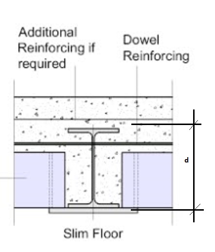
  • We start with a test effective depth of the slab, d, as shown on the top diagram.

This d is worked out following these steps.

  • multiplying the area of concrete on top by its equivalent steel using a factor of:

$$N= \frac{ E_{concrete}}{E_{steel}}$$

  • Then we add this equivalent area of concrete to the top steel flange and find their centroid.

  • Then we assume a test plate we area $a $ and find the centroid of this plate with the lower flange. We know in a composite beam tension, T is equal to compression, C.

  • $T=C=M/D$

  • We compare $T\ $ with the $T_{ available}$ by multiplying the lower flange + plate area by 36kpsi or the allowable strength of the steel.

  • If $ \ T>T_{available\ }$ we add to the area of the plate and test agin, till $T\leq T_{available}$

Then we calculate the beam using code equations and check for deflection and shear. and deflection

detail

composite beam

$\endgroup$
5
  • $\begingroup$ I think the OP is asking how to determine the thickness of the cover plate (US) of a built-up beam (I beam + cover plate). $\endgroup$
    – r13
    Commented Dec 21, 2021 at 21:54
  • $\begingroup$ As r13 says. Added a sketch for clarity $\endgroup$
    – Stilez
    Commented Dec 21, 2021 at 22:45
  • $\begingroup$ Yes i agree. cover plate on the bottom of the steel beam. i thoght thats wath i meant. the cover plate has to be calculated as part of the concret- steel composite beam. $\endgroup$
    – kamran
    Commented Dec 21, 2021 at 22:47
  • $\begingroup$ The problem is that its the main "I" beam that takes the load of the concrete floor beams. But one can imagine if the underslung steel plate was 1mm thick it would crumple and the beam fall through, and if it was 40mm thick it would be incredibly excessive. So there ought to be a calculation similar to beam calcs, where there's an acceptable distortion level (%, mm, angular, don't know which), and a calc that says for a given loaded floor beam on a given thickness of underslung plate, the design/expected distortion. Its that aspect, UK/EU design criterion for the plate in my sketch, I'm after $\endgroup$
    – Stilez
    Commented Dec 21, 2021 at 22:54
  • $\begingroup$ How that works. I can't find it out or figure it out. $\endgroup$
    – Stilez
    Commented Dec 21, 2021 at 22:55

Your Answer

By clicking “Post Your Answer”, you agree to our terms of service and acknowledge you have read our privacy policy.

Not the answer you're looking for? Browse other questions tagged or ask your own question.