0
$\begingroup$

First off I'm not an engineer so please excuse the simple language I use to explain my question!

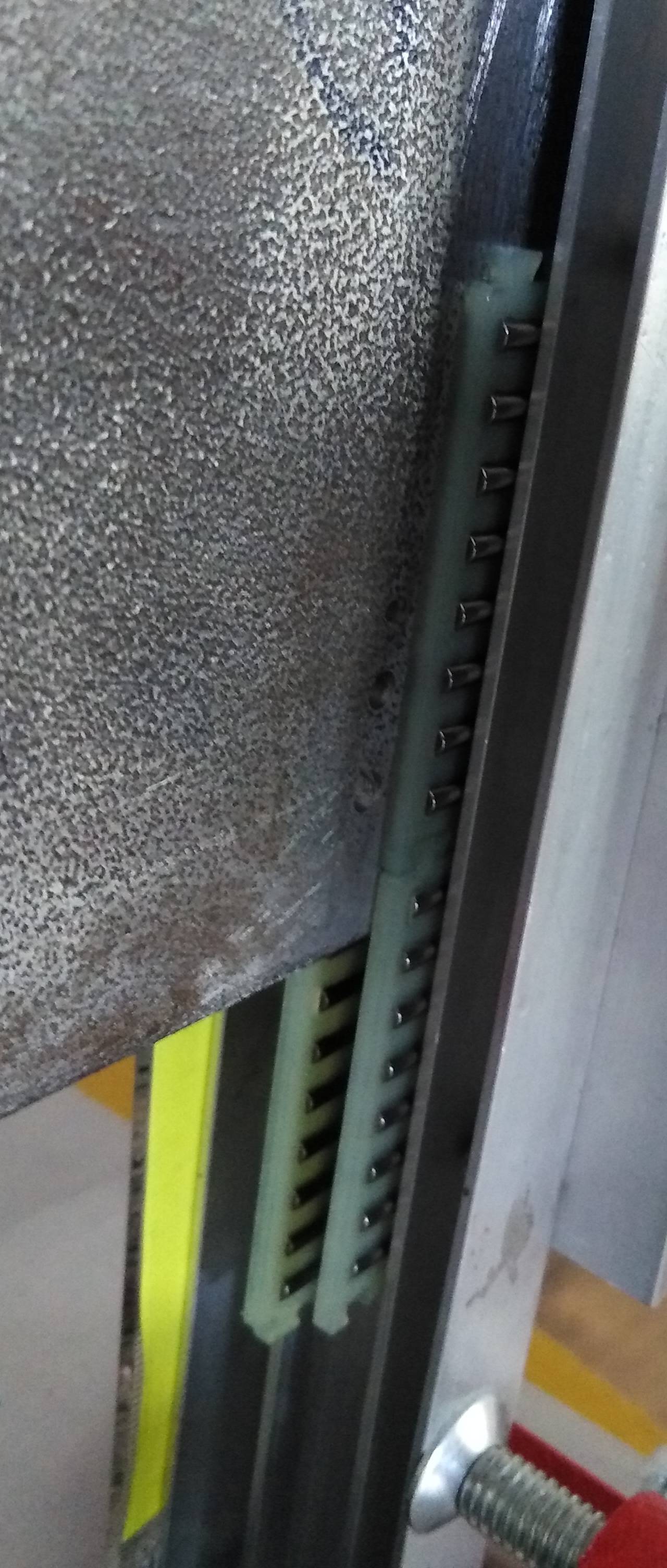
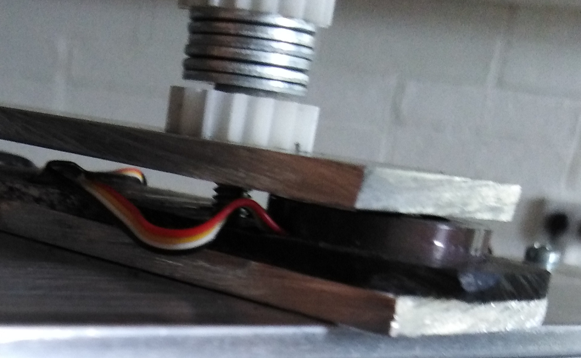
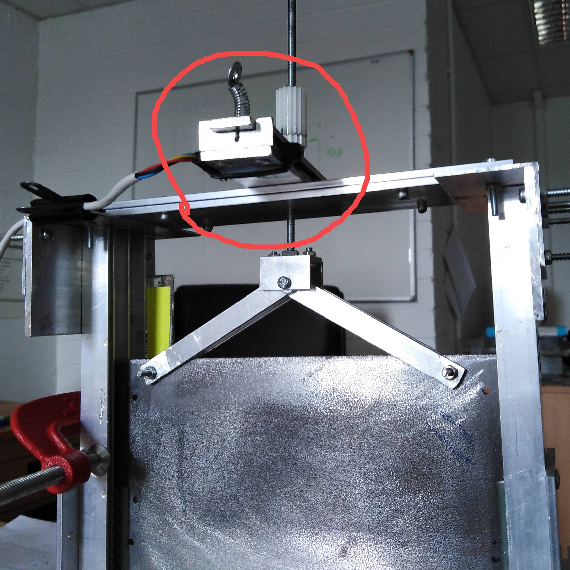
I have an arrangement whereby I have a steel plate suspended from basically a bridge. The plate is free to move up and down, guided in a channel by needle rollers. The vertical movement is controlled by an M4 threaded rod, with a load cell between the top of the bridge and the M4 nut, which is screwed in and out to effect movement. Hopefully the three images will convey what I'm doing.

The steel plate and its attachments weigh ~800g. If I suspend this outside of my test jig,I get a consistent mV output in line with what I expect to see.

However, if I raise the plate via the control nut, I can get an output that works out as 970g, and going down the reading can drop to 630g. It's not always this bad, but it was easy to re-produce this range, Note, readings are taken after leaving it to settle.

Plate appears to move very freely (just by feel), and rollers are well oiled (WD40).

Can anyone explain what is happening here, and how to overcome it, or allow for it?

Thanks!

enter image description here
enter image description here

enter image description here

enter image description here

$\endgroup$
10
  • $\begingroup$ Your plate looks rough. Is it squeezed between the rollers? $\endgroup$
    – DKNguyen
    Commented Jul 13, 2021 at 14:03
  • $\begingroup$ @DKNguyen, unfortunately you are correct, it was the best I could source. I did however smooth the edges where the rollers sit, as best I could with a file. But. perhaps this is my issue? It is not squeezed too much. Seems to move freely. $\endgroup$
    – KevInSol
    Commented Jul 13, 2021 at 14:08
  • $\begingroup$ It's a daunting task to smooth long edges with a file while also keeping the edges parallel. What about the edges running through the noodle rollers? Do those touch? What happens if you tap the setup with a rubber mallet? $\endgroup$
    – DKNguyen
    Commented Jul 13, 2021 at 14:10
  • $\begingroup$ @KevinSol I find it very suspicious that its exactly $\pm$170g from 800g. When you are dropping it down is it supported somewhere? Could you provide a few more measurements/details on the process? $\endgroup$
    – NMech
    Commented Jul 13, 2021 at 14:10
  • $\begingroup$ Could you check how much does the plate by itself weighs? $\endgroup$
    – NMech
    Commented Jul 13, 2021 at 14:27

1 Answer 1

3
$\begingroup$

When you are raising the plate you are also raising the bearings and since they need to roll there is the frictional component pulling down on the bearings and pulling down on the plate.

When you lower the system you are pulling the bearings down and since they again need to roll there is the frictional component pulling up on the bearings and pulling up on the plate.

Adding a vibrating source, to jiggle the system, may help minimize the error. Another way to minimize error is to measure the load uni-directionally (measure the load in one direction only). That is, to lower the system, but then raise it slightly to bias residual loads in one direction. Thus, only measure the load while being raised slightly.

I would postulate, if you removed the bearings and allowed the plate to "clatter" between the guide edges the forces would compare favorably.

I'm not really sure why you would want to know the weight of the raising and lowering system unless you really expected it to change because of added mass during operation. If you can live with the frictional components so be it. If you expect service is to be required occasionally, then you might plan for occasional maintenance.

The load cell could provide the information of service being required, as the measured load separation between raising and lowering (as you have measured) expand.

I would venture that this is for controlling water flow in rectangular concrete channels. If dirt channels, your bearings are likely to get real dirty.

If you want to gage water flow over time, I would say, use a V-notch weir or a rectangular weir down stream of the "gate". The down stream level of the water should be below the bottom of the V or the "rectangle". Water flow is a function of the up stream level of water above the bottom of the V or "rectangle".

If the gate is partially submerged in water, then the weight of the gate will be diminished by the weight of displaced water by the volume of the partially submerged (wetted) gate.

$\endgroup$
5
  • $\begingroup$ Thank you, I read your comments and was about to reply there. Yes, indeed if I remove the bearings the up/down is the same within a decimal point. I'll try your uni-direction idea tomorrow. I believe your explanation re the bearings adding forces. If I understand correctly, when going down, it actually pushes up giving a lower then actual weight? $\endgroup$
    – KevInSol
    Commented Jul 13, 2021 at 17:12
  • $\begingroup$ Yes, and vise-versa. $\endgroup$
    – Jim Clark
    Commented Jul 13, 2021 at 18:19
  • $\begingroup$ @JimClark I'm trying to correct "slghtly" for the third time, to make the spelling as perfect as its content, but you keep making changes. ... NEver mind you got to it. :) $\endgroup$
    – NMech
    Commented Jul 13, 2021 at 18:23
  • $\begingroup$ Thank you NMech. $\endgroup$
    – Jim Clark
    Commented Jul 13, 2021 at 18:42
  • $\begingroup$ I tried your uni-direction idea and it seems to give very good results. So, going up I just stop, but going down I give it a half turn (0.35mm) back up. I'm happy to have a reading a little over in both directions. This is just a test jig to try out something, nothing to do with water, but thank you for exploring that possibility. $\endgroup$
    – KevInSol
    Commented Jul 14, 2021 at 13:53

Your Answer

By clicking “Post Your Answer”, you agree to our terms of service and acknowledge you have read our privacy policy.

Not the answer you're looking for? Browse other questions tagged or ask your own question.