I'm building a Wien Bridge oscillator. The oscillation part works just fine, but it currently limits on the supply rails.
I want to add amplitude control, so I've added a precision rectifier which feeds an integrator that controls an LDR to change the gain of the circuit.
This setup makes the output amplitude oscillate. To get a better understanding of what happens I want to construct a block diagram of the amplitude control and use control theory to improve the design.
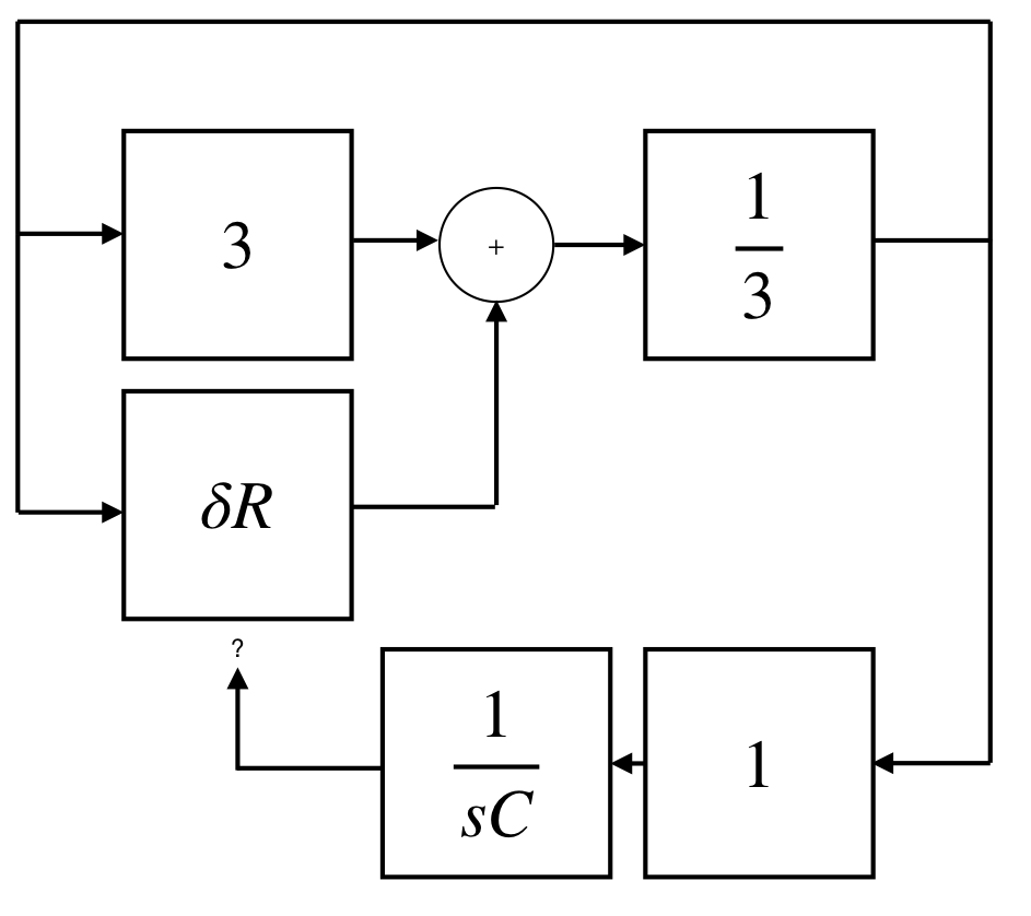
I'm already a bit stuck on building the block diagram. I've the following:
 Where the 3 is the ideal gain, to compensate the $\frac{1}{3}$ of the frequency selective network. The $\delta R$ is the change in the gain resistor due to the LDR. Since the frequency selective network has 0 phase shift at the oscillation frequency I believe there is no need to put in an actual transfer function.
I've modelled the rectifier with a gain of 1, as it doesn't really change the amplitude it just presents it in a different form. The $\frac{1}{sC}$ is the integrator.
Is this somewhat correct? How can I now add the fact that the integrator output alters the $\delta R$?