Are there some general guidelines for approximating the plastic modulus of steel under tension so that a bilinear stress strain curve can be defined for Loading beyond the elastic region?
-
$\begingroup$ Most applications avoid loading steel outside the elastic region, why would you consider it? $\endgroup$– Solar MikeCommented Dec 21, 2017 at 18:35
-
$\begingroup$ Unfortunately it is one of those applications and is unavoidable. It is localized. Sometimes it is under yield sometimes its over the yield. I am not aware of any guidelines to help specify an approximate plastic modulus $\endgroup$– shogganannaCommented Dec 21, 2017 at 19:57
-
$\begingroup$ Assume the worst case scenario; perfect plasticity. Hardening modulus $\sim$ 0. This is actually not a bad approximation for many steels. $\endgroup$– Biswajit BanerjeeCommented Dec 21, 2017 at 22:42
-
$\begingroup$ How would this be a worse case scenario? Perfectly plastic:This would mean the capping of any stresses higher than the yield stress. I would then be forced to look at the amount of plastic straining. $\endgroup$– shogganannaCommented Dec 21, 2017 at 22:48
-
$\begingroup$ Worst case => low yield stress: yield stress increases => material becomes stronger. Plasticity makes no sense without considering plastic deformation. It's plastic deformation that causes failure, not a particular value of stress. $\endgroup$– Biswajit BanerjeeCommented Dec 22, 2017 at 5:06
4 Answers
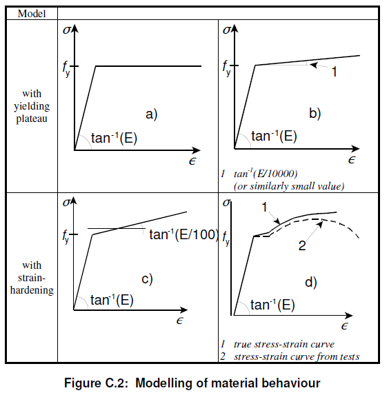
Eurocode 1993-1-5 Design of Steel Structures - Plated structural elements, Annex C Clause C.6 Material properties allows the following assumptions:
a) elastic-plastic without strain hardening (i.e. elastic-perfectly plastic)
b) elastic-plastic with a nominal plateau slope (this uses a very small young's modulus post-yield, E/10000, to help with convergence difficulties experienced in finite element analysis)
c) elastic-plastic with linear strain hardening (this uses E/100 to model the post-yield young's modulus)
d) true stress-strain curve modified from test results
Option c would be applicable for your situation: beyond the elastic region you can approximate the Young's Modulus as 1/100th of the elastic Young's Modulus.
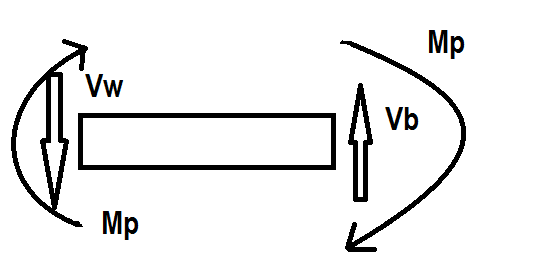
For a localized plastic loading, you may want to consider the plastic hinge model. In this model, it is assumed that the moment the beam reaches yield stress, it becomes a plastic hinge. Here is a freebody diagram of the plastic hinge:
Note that the shear at the wall ($V.w$) and the shear at the hinge ($V.b$) may be different, but the plastic moment is still the same - the plastic stresses have redistributed the loading so that less load occurs at the wall, and more of the load can be supported at the hinge point.
The plastic hinge model doesn't use the normal second moment of area, but utilizes the plastic section modulus as well as the yield stress to find the ultimate allowable plastic moment. As an example, while a normal rectangle would be $\frac{bh^2}{6}$, in plastic sections it would be $\frac{bh^2}{4}$. Multiply by a yield stress of a hypothetical $100 MPa$ would generate a final moment. Using these methods, we would generate a free-body diagram of each side of the hinge, solve for the different values of $M_p$, and find out which loading causes $M_p$ to reach the ultimate value determined above. This would be the final allowable forces, and the point of plastic rupture.
-
$\begingroup$ Irrelevant to a stress-strain curve, the OP wants a plastic Young's modulus $\endgroup$– AndyTCommented May 28, 2019 at 15:37
Plastic yield stress is the stress above the linear part of stress strain curve and varies by the class of steel. When a member is stressed beyond this limit it will strain by larger amounts and it won't relax back to original geometry. However while in deforming in plastic range the section can absorb huge amounts of energy and provide the critical short relief safety from disasters such as earthquake or explosion before total collapse of the structure .
In structural engineering this property of steel is taken advantage of by designing the connections and members of structure to encourage plastic hinge at prescribed locations such as to save a column at the expense of a beam by tapering the flanges of the beam just before the joint to a narrower width, thus providing a ductile behavior under above strength limits of loads.
Even though a section can be stressed in such a way as to experience both elastic and plastic stresses at the same time on different parts of profile common practice to calculate plastic module is this:
Find the neutral axis of the section, in I beams and typical symmetrical sections it's the horizontal axis of symmetry. Find the center of geometry of the top and bottom parts. Multiply top part area by its moment arm, which is the distance from its center of geometry to the neutral axis, then do the same for bottom part and add the result. This is the section's plastic module. Now you can multiply this by the Fy to get the plastic strength of the section.
-
$\begingroup$ Irrelevant to a stress-strain curve, the OP wants a plastic Young's modulus $\endgroup$– AndyTCommented May 28, 2019 at 15:37
The plastic section modulus can be calculated for a given cross section by:
- Locating the plastic neutral axis. PNA
- Bringing the stress distribution to full plastic stress (constant) above and below the PNA.
- Summing the moments on the cross section.
- Finally divide the resulting moment by the yield stress to find the plastic section modulus.
Designing structural steel to perform in it's plastic deformation region is one of the pillars of good seismic design. It is very common to consider the strength of lateral elements and connections post elastic behavior.
-
$\begingroup$ Irrelevant to a stress-strain curve, the OP wants a plastic Young's modulus. $\endgroup$– AndyTCommented May 28, 2019 at 15:36

