Topic #1 - Valve selection, valve operation and flow throttling.
I checked the “minor” head loss for accessories listing the Gate valve (I presume a wedge gate one) operated at intermediate position. To confirm, I downloaded the full article (@researchgate) where it appears as Table 7, but it is not indicated which reference it is based on. An issue in that Table is to list data for a wedge gate (I assumed as as wedge type, a common type used in industrial piping and pipelines - like API600 std) hinting to operate at 25%, 50% or 75% positions. Something that was not said in the article, but I understood you might have extracted data to make your table, was because it presented head loss references for some intermediate position of gate-valvea “gate valve”.
The
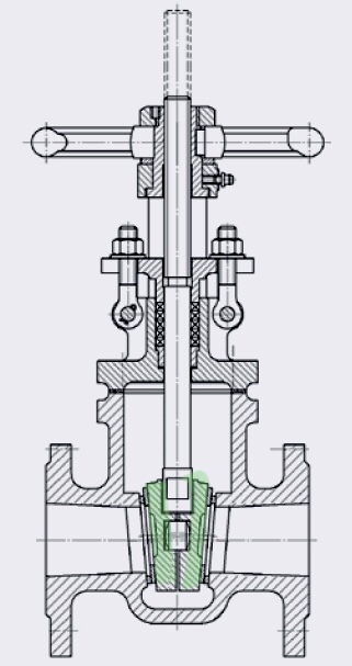
However, when operated in intermediate positions, the gate part (above picture in green) will oscillate, dangling loosely-guided inside the valve body. It would aggravate or not, depending of the flow rate and also of valve orientation (e.g. horizontal or vertical up/down flow); because of that, the actual head loss coefficient would be uncertain on a larger margin. AndSo valve wear will happen and result in early failure.
However,Side note: I found a short 4 min animation of a wedge gate valve and another longer (40 min) from L&T valves showing most constructive and design features and points of attention.
Getting back on track: it is simply not-recommended to modulate a flow using a gate valve. Restricting a flow with a slab-gatespecial slab-gate valve is is already a bad choice and using a wedge-gate valve is just really sad & worse.
Reading the referred article, we see the emphasis is on the thermal analysis of heat-exchangers and the author selected a ball valve for its lower localized head loss - a good choice for that, but that’s it.
Don’t take that data too seriously, as the article simply dumps the head loss data there, no clear units were provided, and readers (as us here) can only make conjectures where it came from.
I prefer to use data from better known tables as here or here, both based on the equivalent length method to estimate the head-loss of fittings and valves; see below the reference to Crane’s TP-410 too.
Topic #2 - “Minor” and Localized“Localized” designations of head losses.
Although it is common to see the denominations of Major“Major” and Minor“Minor” wording to head-losses losses in English, the “minor”minor head losses are more likely in long pipelines, but this designation can be misleading for piping systems because these localized head losses (as in fittings and valves) can be bigger than the “major”major ones (attributed to piping frictions), as others highlight it too, as in here (Introduction, parag.#4) and here (see misnomer).
That is why I prefer to use terms as localizedlocalized and distributeddistributed head losses. The localized term is for fittings and valves, while the distributed term goes for piping.
Depending of the comparative “equivalent length” of Depending of the comparative “equivalent length” of fittings&valves versus the actual pipingfittings&valves versus the actual piping length, head loss can be major and minor respectively, especially if a valve is throttling or modulating the flow - as globe, needle and choke valves do - or if an orifice plate is used.
This comes from the way head-losses are modeled to be computed when using “Darcy-Weisbach equation for a pipe flow”, as you said in the beginning.
ButNote that most valves even fully open (with rare exceptions) perturb the flow much more than the length in the piping would do. The exceptionsexceptions are mostly through-conduit valves, where the fullslab-bore ballgate valve is a common example and a full-bore ball valve is another.
Because of that, you simply count the overall length of the piping line (= pipe with fittings and valves) to calculate the distributed losses. Using the equivalent length method, then you add theeach localized loss for each fitting/valve’s equivalent length of- or use the localized lossesK values (your decision).
AlsoRemember that when we select the value of “K” or “L.equivalent” for a given valve, this is just an approximationa modeled approximation from actual experimental data; observing numbers more closely (i.e. higher number of significant digits/figures), it also varies from manufacturer A to B.
Another source of (small) inaccuracy when using comes from the use of “Table of Colebrook equation approximations”, for non-iterativewith equations that are calculated faster computationally (nonbeing non-iterative), they show deviations of variable degree when compared with the results obtained for Colebrook’s coefficient iterative calculationcalculations.
So, there are several contributors to the overall uncertainty of the computer-based modeled solution. Similarly adequate methods give results that would numerically vary, obviously, but to a smaller degree that is within the uncertainty (or inaccuracies) of the models and approximations used, if their boundaries and limitations (as Reynolds, fluid properties, heat transfer, piping geometry, fluid state, etc) are respected.
Not exactly - see “especially if” highlighted considerations, in Topic #2, above.
I invite other EngineerEngineering fellows here to share their good, practical and reliable piping & hydraulic system titles (sites, textbooks, etc). Adding them to the Comment sectioncomment section would be greatly appreciated.
