added 15 characters in body
Source Link
Pete W
  • 1.6k
  • 1
  • 5
  • 11

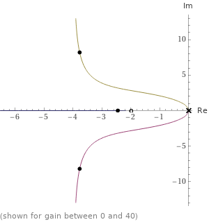
This doesn't address the optimization, but is a follow-up to the comment about the system itself. Below are the 2 qualitative scenarios for a lead compensator with a double-integrator plant.

In the first case, the "best" damping ratio is limited because the root locus can only come so close to the real axis. You may also be limited by max practical gain or frequency.

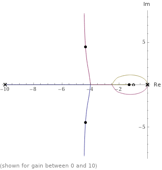
As you continue to movespread apart the zero further rightand pole of the lead, it transitions into the shape of the second example. That second root locus can get you to the real axis, but you can't turn the gain up too high or else the poles depart the real axis again, as seen on the vertical branches on the left. However if the gain is not high enough, there is too much space between the zero and the CL's dominant pole, so you get mid-band gain (step response overshoot) because of that. You can eliminate the overshoot by moving the zero to the feedback path, but then you ruin your bandwidth.

So with a lead compensator it's a tradeoff. Any optimization could reflect that, just be sure to think about the constraints you give it.

Example 1: $$\frac{(1+s/2)}{(s^2)(1+s/10)}$$

example-1

Example 2: $$\frac{(1+s/1)}{(s^2)(1+s/10)}$$

example-2

(plots made with Wolfram Alpha, per the links)
This doesn't address the optimization, but is a follow-up to the comment about the system itself. Below are the 2 qualitative scenarios for a lead compensator with a double-integrator plant.

In the first case, the "best" damping ratio is limited because the root locus can only come so close to the real axis. You may also be limited by max practical gain or frequency.

As you continue to move the zero further right, it transitions into the shape of the second example. That second root locus can get you to the real axis, but you can't turn the gain up too high or else the poles depart the real axis again, as seen on the vertical branches on the left. However if the gain is not high enough, there is too much space between the zero and the CL's dominant pole, so you get mid-band gain (step response overshoot) because of that. You can eliminate the overshoot by moving the zero to the feedback path, but then you ruin your bandwidth.

So with a lead compensator it's a tradeoff. Any optimization could reflect that, just be sure to think about the constraints you give it.

Example 1: $$\frac{(1+s/2)}{(s^2)(1+s/10)}$$

example-1

Example 2: $$\frac{(1+s/1)}{(s^2)(1+s/10)}$$

example-2

(plots made with Wolfram Alpha, per the links)
This doesn't address the optimization, but is a follow-up to the comment about the system itself. Below are the 2 qualitative scenarios for a lead compensator with a double-integrator plant.

In the first case, the "best" damping ratio is limited because the root locus can only come so close to the real axis. You may also be limited by max practical gain or frequency.

As you continue to spread apart the zero and pole of the lead, it transitions into the shape of the second example. That second root locus can get you to the real axis, but you can't turn the gain up too high or else the poles depart the real axis again, as seen on the vertical branches on the left. However if the gain is not high enough, there is too much space between the zero and the CL's dominant pole, so you get mid-band gain (step response overshoot) because of that. You can eliminate the overshoot by moving the zero to the feedback path, but then you ruin your bandwidth.

So with a lead compensator it's a tradeoff. Any optimization could reflect that, just be sure to think about the constraints you give it.

Example 1: $$\frac{(1+s/2)}{(s^2)(1+s/10)}$$

example-1

Example 2: $$\frac{(1+s/1)}{(s^2)(1+s/10)}$$

example-2

(plots made with Wolfram Alpha, per the links)

added 48 characters in body
Source Link
Pete W
  • 1.6k
  • 1
  • 5
  • 11

This doesn't address the optimization, but is a follow-up to the comment about the system itself. Below are the 2 qualitative scenarios for a lead compensator with a double-integrator plant.

In the first case, the "best" damping ratio is limited because the root locus can only come so close to the real axis. You may also be limited by max practical gain or frequency.

As you continue to move the zero further right, it transitions into the shape of the second example. That second root locus can get you to the real axis, but you can't turn the gain up too high or else the poles depart the real axis again, as seen on the vertical branches on the left. However if the gain is not high enough, there is too much space between the zero and the CL's dominant pole, so you get mid-band gain (step response overshoot) because of that. You can eliminate the overshoot by moving the zero to the feedback path, but then you ruin your bandwidth.

So with a lead compensator it's a tradeoff. Any optimization could reflect that, just be sure to think about the constraints you give it.

Example 1: $$\frac{(1+s/2)}{(s^2)(1+s/10)}$$

example-1

Example 2: $$\frac{(1+s/1)}{(s^2)(1+s/10)}$$

example-2

(plots made with Wolfram Alpha, per the links)

This doesn't address the optimization, but is a follow-up to the comment about the system itself. Below are the 2 qualitative scenarios for a lead compensator with a double-integrator plant.

In the first case, the "best" damping ratio is limited because the root locus can only come so close to the real axis. You may also be limited by max practical gain or frequency.

As you continue to move the zero further right, it transitions into the shape of the second example. That second root locus can get you to the real axis, but you can't turn the gain up too high or else the poles depart the real axis again, as seen on the vertical branches on the left. However if the gain is not high enough, there is too much space between the zero and the CL's dominant pole, so you get mid-band gain (step response overshoot) because of that. You can eliminate the overshoot by moving the zero to the feedback path, but then you ruin your bandwidth.

So with a lead compensator it's a tradeoff. Any optimization could reflect that, just be sure to think about the constraints you give it.

Example 1: $$\frac{(1+s/2)}{(s^2)(1+s/10)}$$

example-1

Example 2: $$\frac{(1+s/1)}{(s^2)(1+s/10)}$$

example-2

(plots made with Wolfram Alpha, per the links)

Source Link
Pete W
  • 1.6k
  • 1
  • 5
  • 11

This doesn't address the optimization, but is a follow-up to the comment about the system itself. Below are the 2 qualitative scenarios for a lead compensator with a double-integrator plant.

In the first case, the "best" damping ratio is limited because the root locus can only come so close to the real axis. You may also be limited by max practical gain or frequency.

As you continue to move the zero further right, it transitions into the shape of the second example. That second root locus can get you to the real axis, but you can't turn the gain up too high or else the poles depart the real axis again, as seen on the vertical branches on the left. However if the gain is not high enough, there is too much space between the zero and the CL's dominant pole, so you get mid-band gain (step response overshoot) because of that. You can eliminate the overshoot by moving the zero to the feedback path, but then you ruin your bandwidth.

So with a lead compensator it's a tradeoff. Any optimization could reflect that, just be sure to think about the constraints you give it.

Example 1: $$\frac{(1+s/2)}{(s^2)(1+s/10)}$$

example-1

Example 2: $$\frac{(1+s/1)}{(s^2)(1+s/10)}$$

example-2