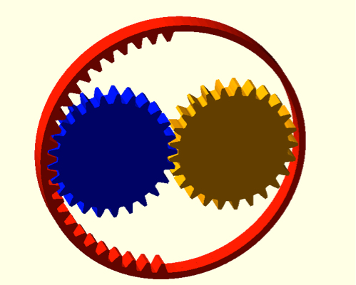
One solution is to use a system with a ring gear that only has teeth on half of its inner circumference, like conceptually shown in the following image:

There are three gears:
- Ring gear (red)
- Alternating gear (blue)
- Output gear (orange)
The alternating gear and output gears can be identical, and the sum of the numbers of teeth of the alternating and output gears should equal that to the ring gear if it had all its teeth instead of half. Otherwise the two inner gears will not properly fit inside the ring gear.
This mechanism works by rotating the ring gear, and the desired alternating motion will be obtained from the output gear. At any one time, the ring gear meshes will one of the inner gears. The inner gear that meshed will the ring gear will rotate in the same direction as the ring gear, causing the other inner gear to rotate in the opposite direction.
For example, let's say we rotate the ring gear CW. If the ring gear meshes with the output gear, the output gear will also turn CW. CW in, CW out. Now, if the ring gear meshes with the alternating gear, the alternating gear turns CW, forcing the output to be ACW. CW in, ACW out: the output shaft has alternated in direction.
The meshing of the ring gear switches between one inner gear to the other every half turn of the ring gear. It is worth noting that the output gear's speed does not change except when the meshing alternates, at which point the speed reverses.
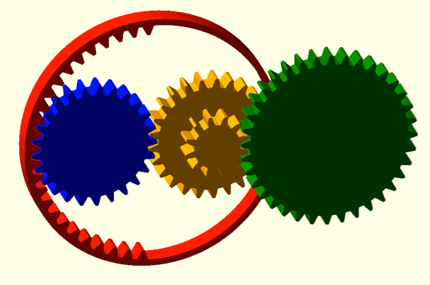
One issue with this concept as-is is that one revolution of the ring gear brings about one full turn of the output gear one way, followed by one full turn the other way: this rotation may be too much for your agitation mechanism. To resolve this, a gear reduction stage should be added to reduce the output rotation:

A gear has been fitted onto the side of the output gear (also orange to indicate its attachment), and this gear meshes with a larger gear (green). The green gear will turn slower and less far than the old orange output gear, and therefore the green gear becomes the new output. Therefore, the amount of rotation of the final output (green) that occurs before the direction alternates, in degrees, $\theta$, can be calculated using the following formula:
$$\theta=360° \cdot N_1/N_2$$
Where $N_1$ is the number of teeth on the gear attached to the side of the old orange output gear, and $N_2$ is the number of teeth on the new green output gear. In the image just above, $N_1=12$ and $N_2=36$, so the rotation angle before direction alternation is 120°. Note that if $N_1 \gt N_2$, you can get more than one output revolution before alternation (although this might not be suitable if the output is subject to high forces resisting motion).
Finally, it should be said that it is possible that, as the meshing transitions from one inner gear to the other, there may be a point where both inner gears are in mesh with the ring gear, jamming the gearset and making mesh alternation impossible. To resolve this, finer gear teeth should be used, as well as removing/filing down one or two of the end teeth on the ring gear to eliminate this dual meshing region.


