26
$\begingroup$

I have an Arduino board with a 9 degree of freedom sensor, from which I must determine the pitch, yaw, and roll of the board.

Here is an example of one set of data from the 9-DOF sensor:

Accelerometer (m/s)

  • $\text{Acc}_{X}$ = -5,85
  • $\text{Acc}_{Y}$ = 1,46
  • $\text{Acc}_{Z}$ = 17,98

Gyroscope (RPM)

  • $\text{Gyr}_{X}$ = 35,14
  • $\text{Gyr}_{Y}$ = -40,22
  • $\text{Gyr}_{Z}$ = -9,86

Magnetometer (Gauss)

  • $\text{Mag}_{X}$ = 0,18
  • $\text{Mag}_{Y}$ = -0,04
  • $\text{Mag}_{Z}$ = -0,15

How can I calculate pitch, yaw, and roll from these data?

$\endgroup$
3
  • 1
    $\begingroup$ Basic principle: from the detection of gravity in your accelerometer you know which way is down; from the detection of the earth's magnetic field in your magnetometer you know which way is North. Based on this and assuming no other significant accelerations or strong magnetic fields you can determine your own attitude. $\endgroup$
    – welf
    Commented Jun 27, 2015 at 0:00
  • 1
    $\begingroup$ Gyroscope data provides a rate of rotation, but not an absolute position. It can be integrated to estimate change from a known attitude, but this is typically noisy and prone to drift if it is not used in conjunction with the other sensors. $\endgroup$
    – welf
    Commented Jun 27, 2015 at 0:05
  • 1
    $\begingroup$ also refer to kalman filters, as the static numbers need to be processed quite a lot, to give reliable estimates of roll-pitch and yaw. Also note that, the position of the sensor is important (you need to take it into account). $\endgroup$ Commented Jun 28, 2015 at 17:24

3 Answers 3

23
$\begingroup$

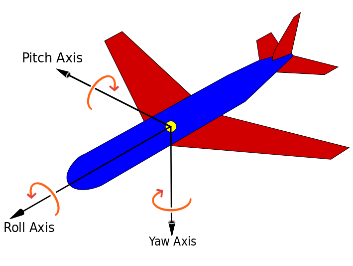
Pitch, roll and yaw are defined as the rotation around X, Y and Z axis. Below as a picture to illustrate the definition.

Roll Pitch and Yaw

In a previous project I used a ADXL345 Accelerometer from Analog Devices to calculate roll and pitch. Below are the equations used to calculated roll and pitch. I have made some of source code available for public use.

accelerationX = (signed int)(((signed int)rawData_X) * 3.9);
accelerationY = (signed int)(((signed int)rawData_Y) * 3.9);
accelerationZ = (signed int)(((signed int)rawData_Z) * 3.9);
pitch = 180 * atan (accelerationX/sqrt(accelerationY*accelerationY + accelerationZ*accelerationZ))/M_PI;
roll = 180 * atan (accelerationY/sqrt(accelerationX*accelerationX + accelerationZ*accelerationZ))/M_PI;

Complete source code can be found here.

Base on the above definitions

yaw = 180 * atan (accelerationZ/sqrt(accelerationX*accelerationX + accelerationZ*accelerationZ))/M_PI;

Note: M_PI = 3.14159265358979323846 it is constant defined in math.h

Below are some references including Arduino base source code that might help you.


References:

$\endgroup$
5
  • 2
    $\begingroup$ Nice answer, it would be worth adding that the position and orientation of the sensor in the vehicle would be important, and that the data must be processed further, to give reliable results. (filtered or fused with more reliable low-frequency data, such as GPS) $\endgroup$ Commented Jun 28, 2015 at 17:26
  • $\begingroup$ (@Zubair) "yaw = 180 * atan (accelerationZ/sqrt(accelerationXaccelerationX + accelerationZaccelerationZ))/M_PI;" what is that 'M_PI'?? $\endgroup$
    – Wasabi
    Commented Apr 22, 2016 at 14:54
  • $\begingroup$ @Wasabi M_PI=3.14159265358979323846. It is constant defined in the math.h library. $\endgroup$ Commented Apr 23, 2016 at 0:59
  • $\begingroup$ why sometimes i find pitch and roll both using pythagoras and sometimes only one uses it $\endgroup$ Commented Aug 9, 2020 at 16:23
  • $\begingroup$ @Mr-Programs, It has been many years since I worked on the problem. I suggest posting a fresh question and linking this response. $\endgroup$ Commented Aug 10, 2020 at 2:50
13
$\begingroup$

So my longer answer below assumes that the board will undergo acceleration and during this time you still need to be able to measure your pitch, roll and yaw within a short amount of time. If the board will be stationary for all measurements then Mahendra Gunawardena's answer will work perfectly for you. If this is going into a device like a segway or model plane or multirotor or anything that moves around, you may want to keep reading. This post is about how to use all three sensors though a method called sensor fusion. Sensor fusion allows you to get the strengths of each sensor and minimize the effects of each sensors weaknesses.

Sensor characteristics and background

First understand that an accelerometer measure all forces being applied to it, not just the force of gravity. So in a perfect world with the accelerometer in a stationary position without any vibrations you could perfectly determine which way is up using some basic trigonometry as shown by Mahendra Gunawardena's answer. However since an accelerometer will pick up all forces, any vibrations will result in noise. It should also be noted that if the board is accelerating you can not just use simple trigonometry as the force the accelerometer is reporting is not only the earths force of gravity but also the force that is causing you to accelerate.

A magnetometer is more straightforward then an accelerometer. Movement will not cause problems with it but things like iron and other magnets will end up effecting your output. If the sources causing this interference are constant its not to hard to deal with but if these sources are not constant it will create tons of noise that is problematic to remove.

Of the three sensors, the gyroscope is arguable the most reliable and they are normally very very good at measuring rotational speed. It is not affected by things like iron sources and accelerations have basically no impact on their ability to measure rotational speed. They do a very good job of reporting the speed at which the device is turning at, however since you are looking for an absolute angle you have to integrate the speed to get position. Doing this will add the error of the last measurement to the error of the new measurements since integration is basically a sum of values over a range, even if the error for one measurement is only 0.01 degrees per second off, in 100 measurements, your position can be off by 1 degree, by 1000 measurements, you can by off by 10 degrees. If you are taking hundreds of measurements a second, you can see this causes problems. This is commonly called gyro drift.

Sensor fusion

Now the beauty of having all of these sensors work together is that you can use the information from the accelerometer and magnetometer to cancel out gyro drift. This ends up allowing you to giving you the accuracy and speed of the gyro without the fatal flaw of gyro drift.

Combining the data from these three sensors can be done in more then one way, I'll talk about using a complementary filter because its far simpler then a kalman filter and kalman filters will eat up much more resources on embedded systems. Often times a complementary filter is good enough, simpler to implement(assuming your not using a pre-built library) and lets you process the data faster.

Now onto the process. The first steps you need to do is to integrate the gyroscope output to convert the angular speed into angular position. You will also most likely have to apply a low pass filter on the accelerometer and magnetometer to deal with noise in the output. A simple FIR filter like the one shown below works here. With some trigonometry you can find the pitch and roll with the accelerometer and the yaw with the magnetometer.

filteredData = (1-weight)*filteredData + weight*newData

The weight is just a constant that can be adjusted depending on how much noise you have to deal with, the higher the noise is the smaller the weight value will be. Now combining the data from the sensors can be done by the following line of code.

fusedData = (1-weight)*gyroData + weight*accelMagData

It should be noted that the data is a vector of the pitch, roll and yaw. You can just use three variables to do this as well instead of arrays if you want. For this calculation the gyro provides a position in degrees in pitch, roll and yaw, the magnetometer provides an angle for yaw while the accelerometer provides its own numbers for pitch and roll.

If you still want more information you can google "sensor fusion with complementary filter" there are plenty of articles about this.
$\endgroup$
4
$\begingroup$

From the accelerator sensor data, you can only calculate pitch and roll. The bellow document from Freescale explains with plenty of information what you need:

AN3461 - Tilt Sensing Using a Three-Axis Accelerometer

Based on the sayings of the document,

$$\tan \phi_{xyz} = \frac{G_{py}}{G_{pz}}$$

$$\tan \theta_{xyz} = \frac{-G_{px}}{G_{py}\sin \phi + G_{pz}\cos \phi} = \frac{-G_{px}}{\sqrt{G_{py}^2 + G_{pz}^2}}$$

which equates to:

roll = atan2(accelerationY, accelerationZ)

pitch = atan2(-accelerationX, sqrt(accelerationY*accelerationY + accelerationZ*accelerationZ))

Of course, the result is this only when the rotations are occurring on a specific order (Rxyz):

  1. Roll around the x-axis by angle $\phi$
  2. Pitch around the y-axis by angle $\theta$
  3. Yaw around z-axis by angle $\psi$

Depending on the rotations order, you get different equations. For the $R_{xyz}$ rotation order, you can not find the angle $\psi$ for the Yaw around z-axis.

$\endgroup$
2
  • 2
    $\begingroup$ He, welcome on the Engineering SE! This site supports Latex, look how beautiful your answer became now. :-) $\endgroup$
    – peterh
    Commented Jun 10, 2018 at 14:11
  • 1
    $\begingroup$ i still don't understand why they have to use Pythagoras for second angle here $\endgroup$ Commented Aug 9, 2020 at 16:35

Your Answer

By clicking “Post Your Answer”, you agree to our terms of service and acknowledge you have read our privacy policy.

Not the answer you're looking for? Browse other questions tagged or ask your own question.